Data collection system and method based on multi-digital path and intercrossed calibration

A data acquisition system and data acquisition technology, applied in signal transmission systems, electrical signal transmission systems, instruments, etc., can solve the problems of great differences in electronic pulse amplitude, inapplicability, and inapplicability of automatic range technology

Inactive Publication Date: 2008-05-28
HANGZHOU RADIANT DIGITAL TECH CO LTD
View PDF0 Cites 9 Cited by
  • Summary
  • Abstract
  • Description
  • Claims
  • Application Information

AI Technical Summary

Problems solved by technology

However, for unsteady signals such as transient electronic signals, automatic range technology cannot be applied, because the amplitude of each electronic pulse may vary greatly
Similarly, for a signal that needs to be measu

Method used


Image

  • Data collection system and method based on multi-digital path and intercrossed calibration
  • Data collection system and method based on multi-digital path and intercrossed calibration
  • Data collection system and method based on multi-digital path and intercrossed calibration

Examples


Embodiment 1

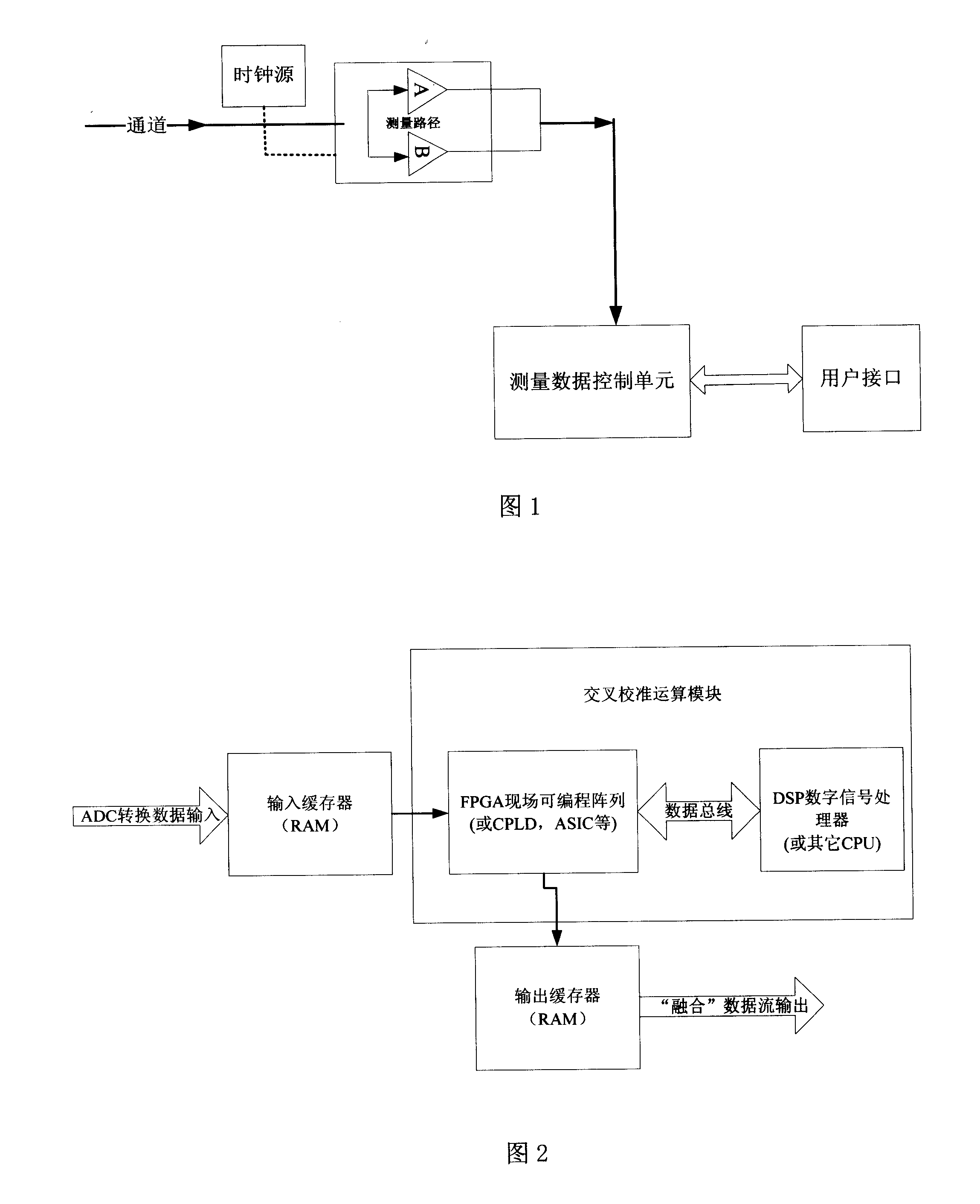
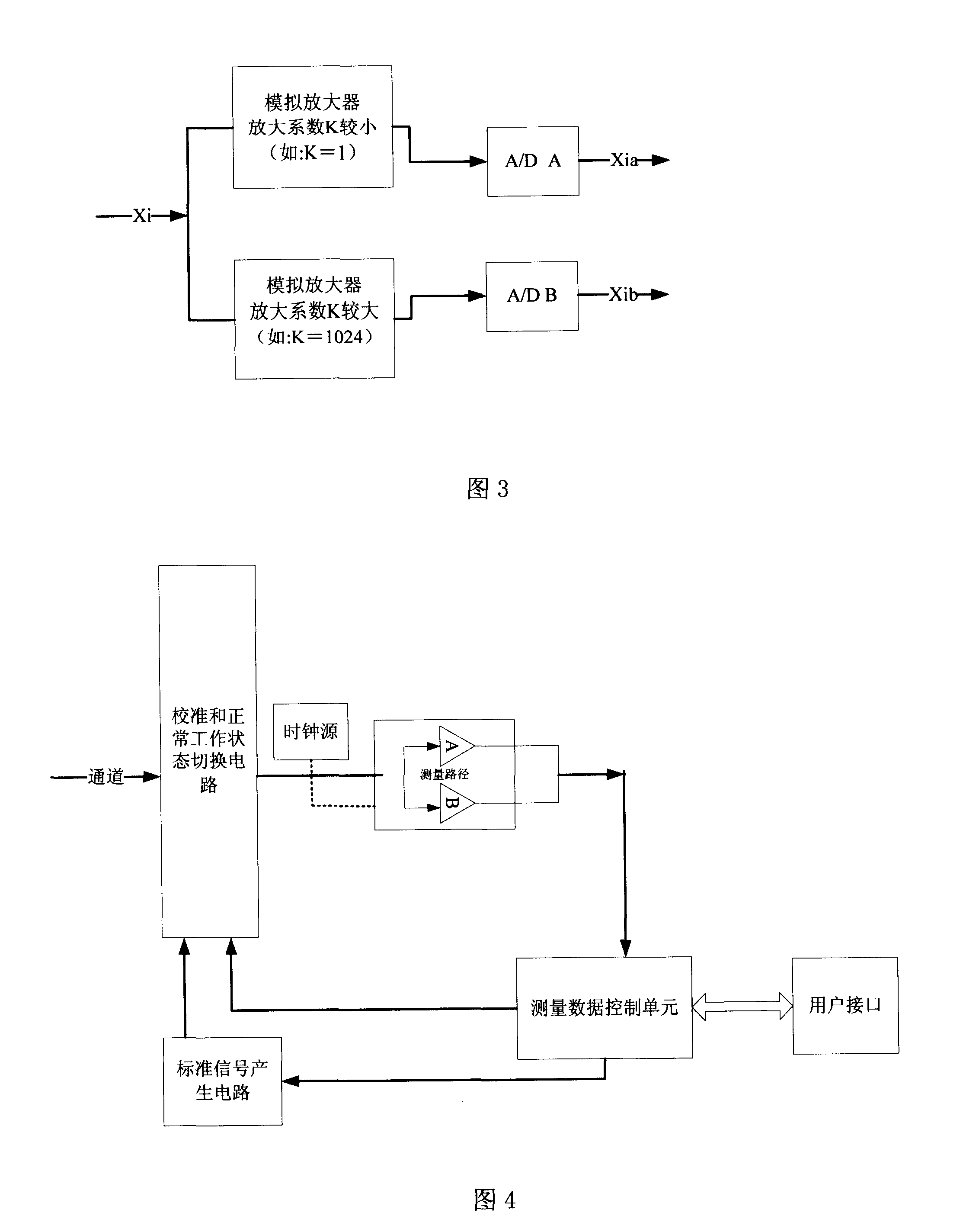
[0019] Embodiment 1: As shown in FIG. 1 , the present invention includes a measurement channel, two measurement paths connected to the measurement channel, and a measurement data control unit connected to each path. The two measurement paths are respectively set as path A and path B, the measurement range of path A is set to 10V, and the measurement range of path B is 0.1V, as shown in Figure 3. Each path contains an analog amplifier and analog-to-digital A / D converter. The amplification factor of the analog amplifier in each path is different, as shown in the figure, the amplification factor of the path A is small, which is set to K=1, and the amplification factor of the path B is large, which is set to K=1024. In addition to the amplifier, attenuators can also be selected for one or more paths according to the actual measurement needs, that is, the magnification ratio is less than 1.0. The measurement data control unit includes an input buffer, an output buffer, and a cross...

Embodiment 2

[0020] Embodiment 2: As shown in FIG. 4 , on the basis of Embodiment 1, a calibration and normal working state switching circuit and a standard signal generation circuit arranged behind the measurement channel are also included. The two are connected with the measurement data control unit, and the standard signal generating circuit is used to generate the reference signal.

Embodiment 3

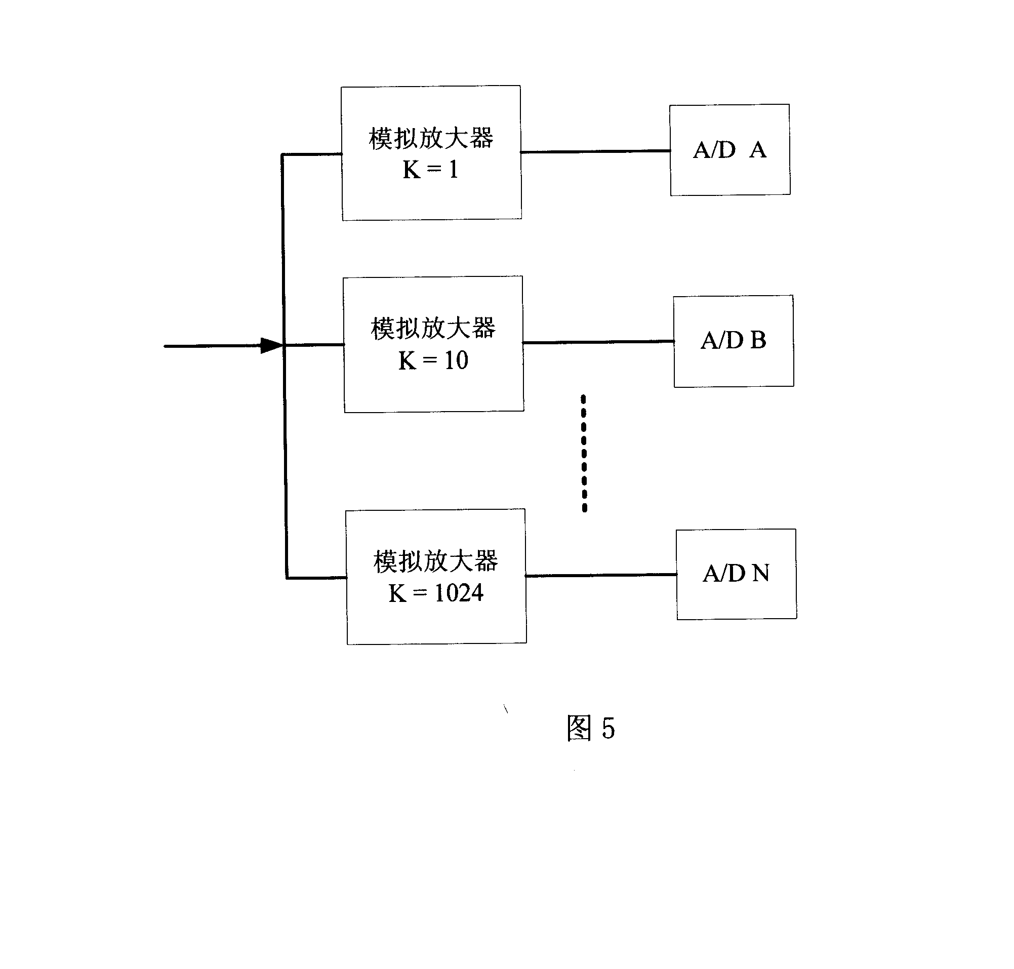
[0021] Embodiment 3: On the basis of Embodiment 2, the measurement path can also be set as more than two measurement systems with more paths with different amplification factors. The structure of its measurement path is shown in Figure 5.

[0022] In actual measurement, for example, we choose a dynamic voltage value to measure, when using the system of embodiment 1 to measure, first input a known reference voltage into the measurement channel, the known reference voltage is in the small range path B Therefore, if the measurement value generated by path B is set to a series of dynamic values ​​YB, then the measurement value YB can be considered as the "best estimate" of the real value. The series of measured values ​​are calculated by the cross-calibration operation module to obtain calibration parameters, if set to ka and Ba. The specific algorithm is as follows: When a series of measured values ​​Yb and Ya are given, how to estimate the coefficients Ka and Ba

[0023] Ya=Ka...


PUM


Abstract

The invention discloses a data collection system based on a plurality of data routes and the cross-calibration and a data collection method adopted the system. The data collection system of the invention comprises a measuring channel, at least two measuring routes connected with the measuring channel and a measured data control unit connected with each measuring route. The measuring channel can be used for receiving input signals. Each measuring route comprises an analog-to-digital converter and an amplifier, the magnification factor of which is different from that of other routes. Each measuring route has a different measuring range. The measured data control unit comprises an input buffer, an output buffer, a cross-calibration computing module consisting of a digital logic circuit and a digital signal processor. The invention has the advantages that the invention can automatically adjust the best measurement range, and the measuring results are more accurate.

Description

technical field [0001] The invention belongs to the field of data acquisition, and in particular relates to a data acquisition system with a high dynamic value input range and a data acquisition method thereof. Background technique [0002] The setting of the input range is one of the most important system settings in the data acquisition system. For example, a test analysis system may need to set a series of different voltage input ranges for each input channel. Whether the input range is set correctly or not can directly affect the quality of the measurement, which is usually described by the signal-to-noise ratio or dynamic range. Due to the uncertainty of the measured signal or the inability to know its amplitude range, it is often very difficult for the user to set the optimal input range. For a data acquisition system with multiple channels and multiple input ranges, it is even more difficult to set the input ranges of all channels properly. To solve this problem, m...

Claims


Application Information

Patent Timeline
IPC IPC(8): G08C19/00
Inventor 诸葛起潘宏
Owner HANGZHOU RADIANT DIGITAL TECH CO LTD
Why Eureka
Try Eureka