Hydraulic pressure reel cart with clutch at transmission last level

A technology of hydraulic winch and clutch, applied in the field of hydraulic winch, can solve the problems of difficult processing, unbalanced force on the power shaft, complex connection structure, etc., and achieve the effects of simple structure, convenient processing and easy installation

Active Publication Date: 2008-06-04
INI HYDRAULIC
View PDF0 Cites 23 Cited by
  • Summary
  • Abstract
  • Description
  • Claims
  • Application Information

AI Technical Summary

Problems solved by technology

[0003] The present invention provides a hydraulic winch with a clutch in the final stage of the transmission with a simple structure and convenient processing and disassembly in order to solve the problems of the existing hydraulic winch with a clutch.
[0004] Another object of the present in

Method used


Image

  • Hydraulic pressure reel cart with clutch at transmission last level
  • Hydraulic pressure reel cart with clutch at transmission last level

Examples


Embodiment 1

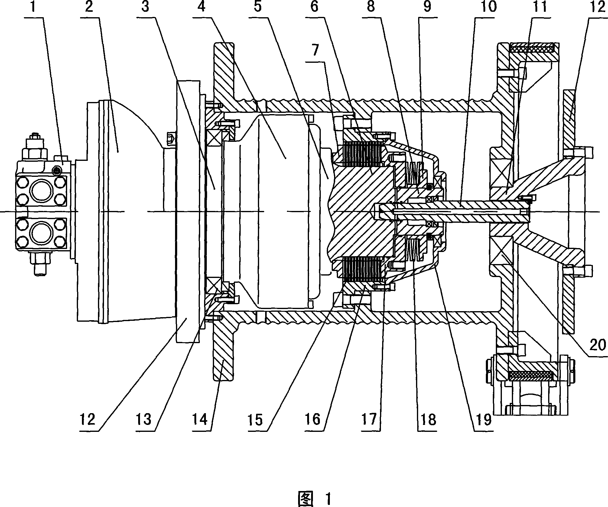
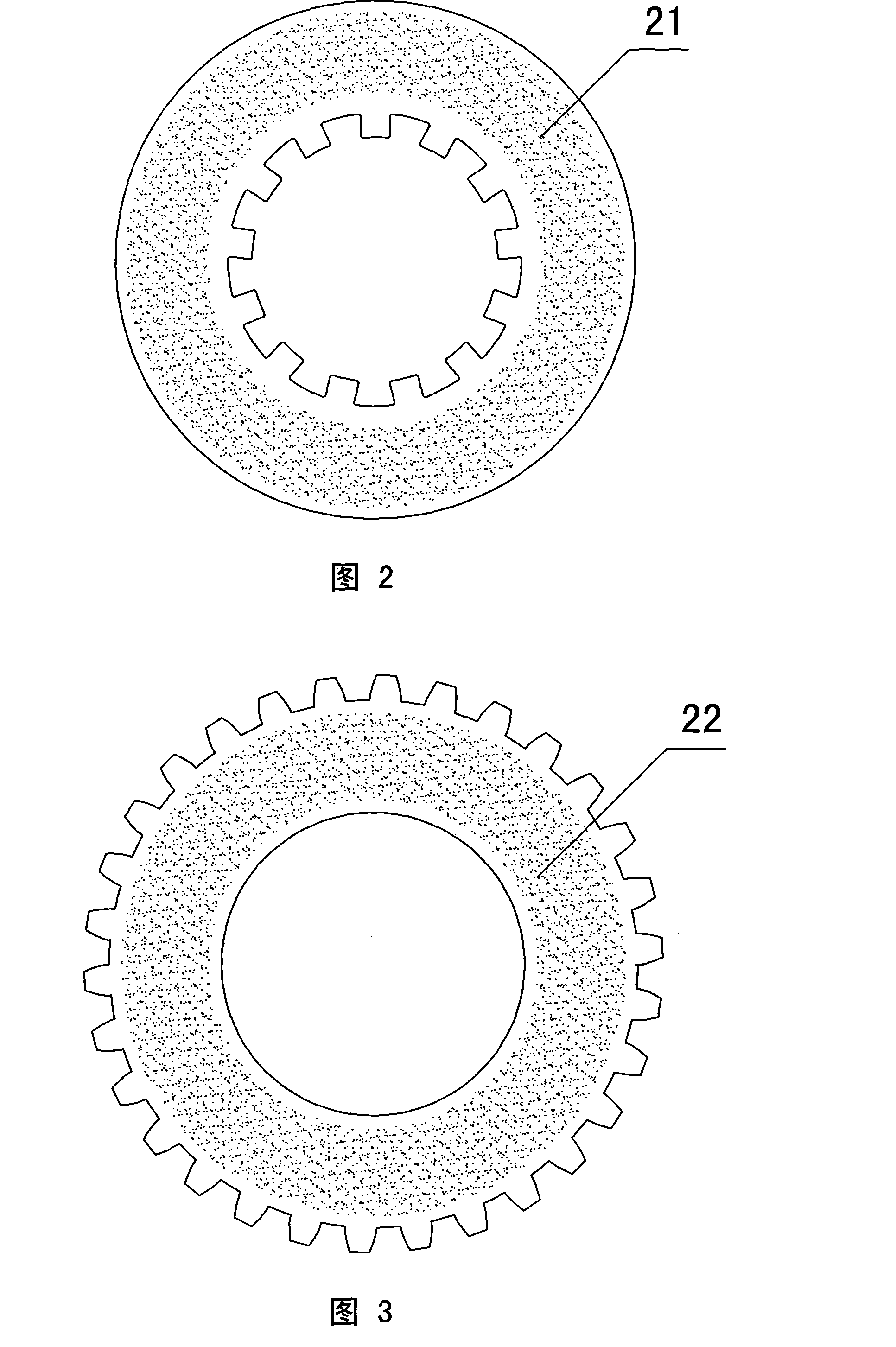
[0018] In Embodiment 1 shown in Figure 1, the hydraulic winch with a clutch at the final transmission stage is composed of a hydraulic motor, a hydraulic brake, a planetary gear reducer, a hydraulic clutch, a reel and a hydraulic control circuit for controlling its work, and is set on the reel. The hydraulic clutch in the barrel 14 is at the end of the transmission chain of the system, the planetary gear reducer 4 is set in the drum 14, and the right output end of the last stage planet carrier 5 is the spline shaft 6 connected to the multi-plate friction clutch. The right end of the spline shaft 6 is exactly the piston 8 of the clutch control oil cylinder, and the spline shaft 6 is connected with an outer cylinder 16 with an internal gear structure through a friction plate 15 . The friction plate is divided into a friction moving plate 21 and a friction fixed plate 22. The inner side of the friction moving plate 21 is provided with a gap suitable for the spline shaft 6, and the...


PUM


Abstract

The invention discloses a hydraulic winch which is provided with a clutch at the transmission terminal. The hydraulic winch which is provided with a clutch at the transmission terminal comprises a hydraulic motor, a hydraulic brake, a planetary gear speed reducer, a hydraulic clutch, a winding drum and a hydraulic control loop which controls the work of the winding drum, wherein the hydraulic clutch arranged in the winding drum is arranged at the terminal of a system transmission chain; the planetary gear speed reducer is arranged in the winding drum, and the output end at the right side of the terminal planetary frame at the terminal of the planetary gear speed reducer is a spline shaft which is connected with a multi-plate type friction clutch; the right end of the spline shaft is the piston of a clutch control cylinder, and the planetary frame of the planetary gear speed reducer, the spline shaft of the clutch and the piston is an integrative structure. The invention effectively overcomes the problems that the present hydraulic winch is complex in connecting structure, difficult in processing and assembly, unbalance in the stress of dynamic shaft, easily worn in the connection part where a frame bearing shaft force, low in mechanical efficiency and short in service life, etc.

Description

technical field [0001] The invention relates to a lifting and lifting working machine, in particular to a hydraulic winch with a clutch at the final transmission stage and using hydraulic pressure as the driving power. Background technique [0002] As we all know, most of the existing hydraulic winches adopt a modular design, that is, hydraulic motors, brakes, planetary gear reducers, etc. are designed as independent components, and then connected together during installation. The announcement date is May 1, 2002 Authorized notification number CN 1346784A discloses a hydraulic winch with a free lowering function, which adopts a similar structural form, but in this structural form of step-by-step connection transmission power, its clutches cannot achieve independent modular design, and their working parts The friction plate clutch and the oil cylinder of the control part need to be installed on the reel and the frame respectively, and cannot be integrated with the planetary r...

Claims


Application Information

Patent Timeline
IPC IPC(8): B66D1/00B66D1/08B66D1/14
Inventor 胡世璇
Owner INI HYDRAULIC
Why Eureka
Try Eureka