Linear voltage-stabilized power supply circuit

A linear stabilized power supply and circuit technology, applied in data processing power supply, electronic switches, electrical components, etc., can solve the problems of increased manufacturing cost, difficulty in motherboard design, and occupation of PCB board space, so as to reduce design difficulty and manufacturing cost, Effect of saving wiring space and required components

Inactive Publication Date: 2010-05-26
HONG FU JIN PRECISION IND (SHENZHEN) CO LTD +1
View PDF1 Cites 0 Cited by
  • Summary
  • Abstract
  • Description
  • Claims
  • Application Information

AI Technical Summary

Problems solved by technology

Due to the different operating voltages of the two types of memory, generally the two types of memory slots have their own independent power conversion modules. On the one hand, this solution uses more components, and on the other hand, it will take up additional PCB board space, resulting in the motherboard design. Increased difficulty and manufacturing costs

Method used


Image

  • Linear voltage-stabilized power supply circuit
  • Linear voltage-stabilized power supply circuit
  • Linear voltage-stabilized power supply circuit

Examples


Embodiment Construction

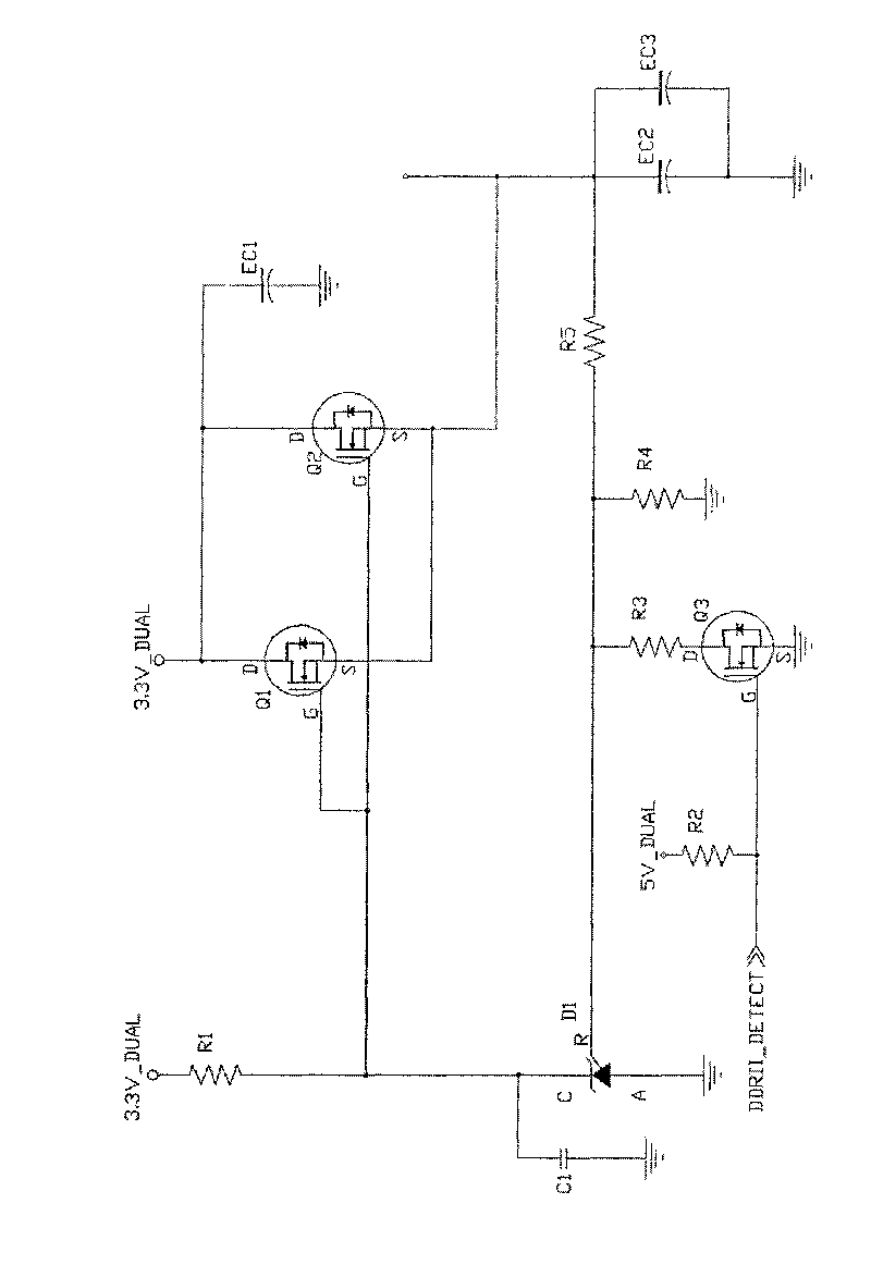
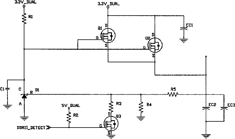
[0008] see figure 1 A preferred embodiment of the linear regulated power supply circuit of the present invention includes a three-terminal adjustable parallel regulator D1, a first field effect transistor Q1 and a second field effect transistor Q2 as output components, an electronic switch (such as a third field effect transistor Q3), first resistor R1, second resistor R2, third resistor R3, fourth resistor R4, fifth resistor R5, first capacitor EC1, second capacitor EC2, third capacitor EC3 and fourth capacitor C1 . The electronic switch used in this preferred implementation mode and the first field effect transistor Q1 and the second field effect transistor Q2 are N-channel depletion type MOS field effect transistors. The anode A of the three-terminal adjustable parallel voltage regulator D1 is grounded, and its cathode C is connected to the power supply of the computer system through the first resistor R1, one end of the third resistor R3, the fourth resistor R4 and the fi...


PUM


Abstract

The invention relates to a linear voltage stabilizing power circuit, which comprises a three-end adjustable parallel voltage stabilizer, an electronic switch, an output assembly, a first resistor, a third resistor, a fourth resistor and a fifth resistor, the anode of the three-end adjustable parallel voltage stabilizer is grounded while the cathode is connected with a power unit through the firstresistor; the third resistor, the fourth resistor and the fifth resistor are connected with a reference voltage end of the three-end adjustable parallel voltage stabilizer, the other end of the thirdresistor is grounded through the electronic switch, the other end of the fourth resistor is grounded; the controlling end of the output assembly is connected with the cathode of the three-end adjustable parallel voltage stabilizer while the input end is connected with the power unit of the computer system and the output end is connected with the other end of the fifth resistor as the output end ofthe linear voltage stabilizing power circuit. The linear voltage stabilizing power circuit can output different voltages according to the different detected signals so as to meet the requirement of different loads, so that the cable laying space and required elements for host machine board can be saved.

Description

technical field [0001] The invention relates to a linear stabilized voltage power supply circuit. Background technique [0002] DDR II SDRAM (Double Data Rate II SDRAM, the second generation of double data rate synchronous dynamic random access memory) is a new generation of memory technology standards developed by JEDEC (Joint Electron Device Engineering Council, Joint Electron Device Engineering Council), and the previous generation of memory Compared with the technical DDRISDRAM (Double Data Rate I SDRAM, the first generation of double data rate synchronous dynamic random access memory) standard, DDR II SDRAM has obvious advantages in pre-reading capability, delay, power consumption, and heat generation. However, since the two memory interfaces have different voltages, they cannot share the same memory slot. At present, in order to facilitate users to upgrade memory, many motherboards integrate two kinds of memory slots, so that DDR I SDRAM and DDR II SDRAM can be used o...

Claims


Application Information

Patent Timeline
Patent Type & Authority Patents(China)
IPC IPC(8): G06F1/26H03K17/687
Inventor 何凤龙胡可友虞恒
Owner HONG FU JIN PRECISION IND (SHENZHEN) CO LTD
Why Eureka
Try Eureka