Golf club and welding method thereof

A golf head and welding method technology, applied in golf balls, golf clubs, welding media, etc., can solve the problems of micro-cracks, low welding speed, poor production efficiency, etc. The effect of speed, improving production efficiency

Inactive Publication Date: 2008-06-11
METAL INDS RES & DEV CENT
View PDF0 Cites 2 Cited by
  • Summary
  • Abstract
  • Description
  • Claims
  • Application Information

AI Technical Summary

Problems solved by technology

However, the method of arc welding must also be welded along the profile track of the metal body and the striking panel, so it also requires a long welding time and causes a low welding speed, so the production efficiency is relatively poor
Furthermore, the arc welding technology will cause air holes and micro-cracks in the welding place, which will affect the joint strength of the golf head
[0004] Regardless of laser welding or arc welding, a raised weld bead will be formed between the metal body and the striking panel after the welding is completed, which still requires time-consuming and manpower-consuming post-processing operations for weld bead grinding, increasing the Cost of production

Method used


Image

  • Golf club and welding method thereof
  • Golf club and welding method thereof
  • Golf club and welding method thereof

Examples


Embodiment Construction

[0031] refer to Figure 2A and Figure 2B , which shows a schematic view of the golf head of the first embodiment of the present invention. The golf head 2 includes a metal body 21 and a metal plate 22 . The metal body 21 has an opening 211, and the opening 211 has a first welding surface 212. In the embodiment, the first welding surface 212 is a right angle. The shape of the metal plate 22 matches the shape of the opening 211, the metal plate 22 is a striking panel, the metal plate 22 has a second welding surface 221, and the second welding surface 221 is opposite to the The first soldering surface 212 . The second welding surface 221 has at least one second bump 222. In the embodiment, the second bump 222 is an annular flange, such as Figure 2C shown. In other applications, the second bump 222 can also be a circular bump, such as Figure 2D shown. Or the second bump 222 can also be an elongated bump, such as Figure 2E shown.

[0032] It should be noted that the fi...


PUM


Abstract

The invention relates to a golf head and a welding method. The welding method comprises arranging a metal plate in an opening hole of a metal body, wherein the shape of the metal plate is matched with the shape of the opening hole, then respectively contacting a first electric pole and a second electric pole with the back surface of the metal body and the top surface of the metal plate, wherein the shape of the first electric pole and the second electric pole are respectively matched with the shape of the bake surface and the top surface, finally conducting electric current through the first electric pole and the second electric pole, and connecting the metal plate and the metal body through the mode of electric-resistance weld. The welding method of the invention is utilized which greatly increases welding speed, raises productivity, and increases the connecting intensity of the weld, simultaneously, a golf head which is welded has high smoothness, and the subsequent processing cost can be reduced.

Description

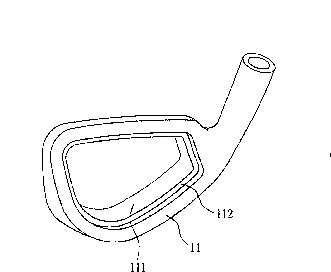
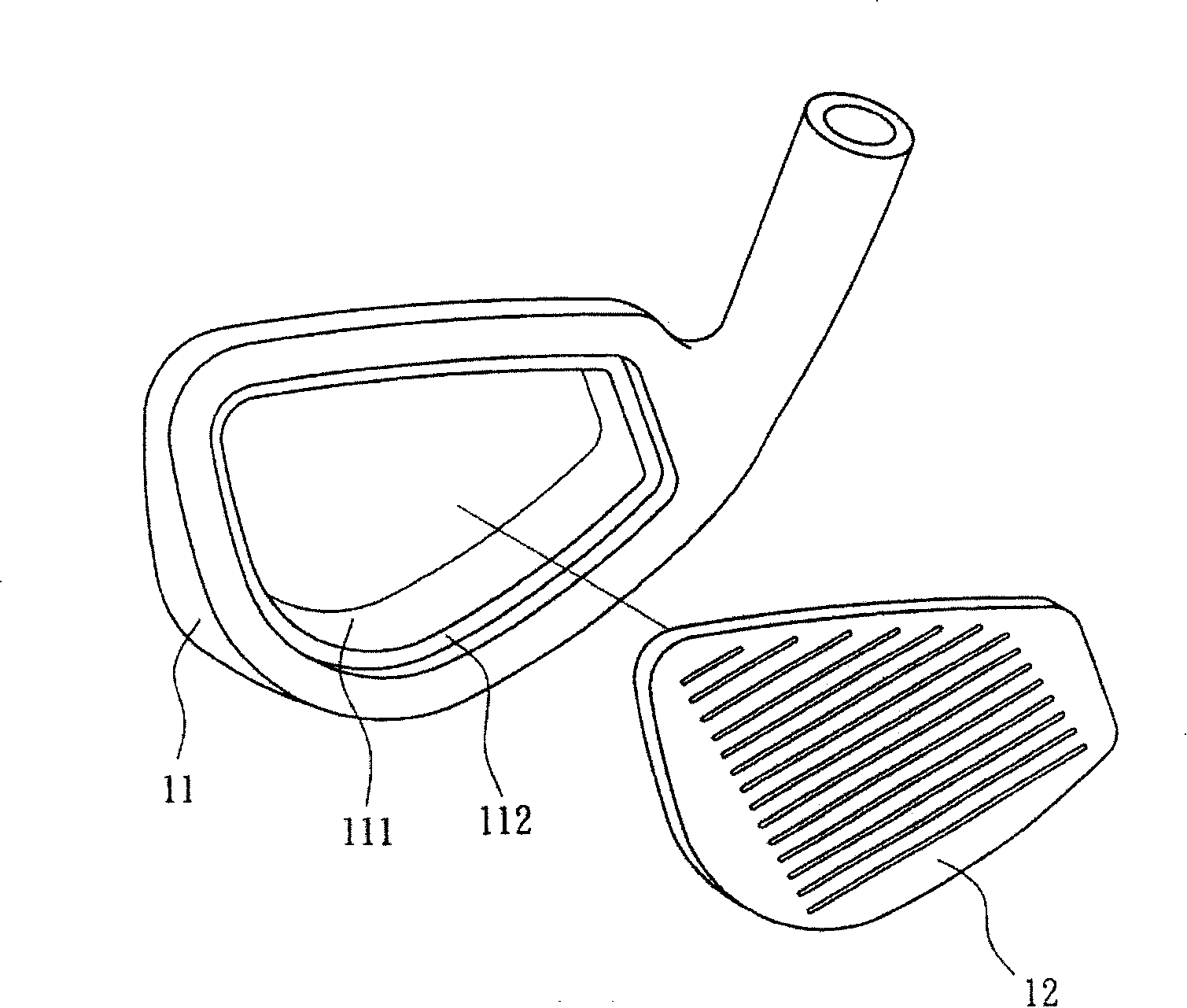
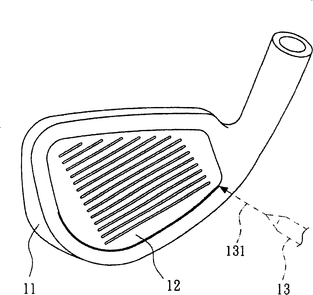
technical field [0001] The present invention relates to a golf head and its welding method, in particular to a golf head utilizing resistance welding and its welding method. Background technique [0002] refer to Figure 1A to Figure 1C , which shows a schematic diagram of a welding method for a conventional golf head. refer to Figure 1A Firstly, a metal body 11 is provided, the metal body 11 has an opening 111 , and the opening 111 has a ring groove 112 . refer to Figure 1B , Next, provide a striking panel 12 , the shape of the striking panel 12 matches the shape of the opening 111 and is arranged on the ring groove 112 . refer to Figure 1C , finally, using fusion welding technology (such as plasma welding or laser welding), in the described embodiment, a laser 131 emitted by a laser device 13 is used to form along the metal body 11 and the striking panel 12 Trajectory welding, so longer welding time is required resulting in lower welding speed, therefore, the produ...

Claims


Application Information

Patent Timeline
IPC IPC(8): A63B53/04B23K11/00B23K35/22B23K11/34A63B102/32
Inventor 汪立德蔡孟修杨子青吕明贤林志伦
Owner METAL INDS RES & DEV CENT
Why Eureka
Try Eureka