Excimer light irradiation apparatus

A light irradiation device and excimer technology, applied in irradiation devices, optics, nonlinear optics, etc., can solve the problems of large amount of inert gas, uneven oxygen concentration, and high manufacturing cost, and reduce the amount of gas used and the processing cost. The effect of increasing the speed and stabilizing the oxygen concentration

Inactive Publication Date: 2011-08-17
USHIO DENKI KK
View PDF3 Cites 0 Cited by
  • Summary
  • Abstract
  • Description
  • Claims
  • Application Information

AI Technical Summary

Problems solved by technology

[0007] However, in the prior art of blowing nitrogen gas onto the substrate 115, there is a large amount of inert gas used, and not only the manufacturing cost is high, but also when the liquid crystal glass substrate and the like are transported, the front end, the center and the rear end of the substrate will be damaged. Oxygen concentration in the part is not uniform, resulting in the problem of processing deviation
and, in Figure 8 In the prior art device shown, the space above the inert gas circulation part is not replaced by nitrogen or the like, so the concentration of oxygen entrapped in the nitrogen gas blown onto the substrate surface is severely uneven, and the same as Inhomogeneity of oxygen concentration corresponding to serious processing deviation problem

Method used


Image

  • Excimer light irradiation apparatus
  • Excimer light irradiation apparatus
  • Excimer light irradiation apparatus

Examples


no. 1 example

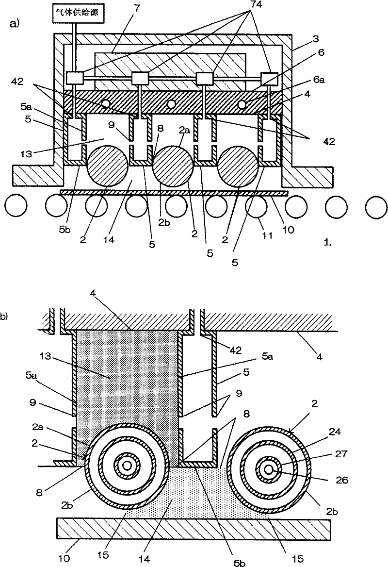
[0040] As a first example, figure 1 shows the excimer photoirradiation device of the present invention. figure 1 - a) is a schematic cross-sectional view of the excimer light irradiation device 1 cut along a plane perpendicular to the tube axis direction of a plurality of approximately rod-shaped excimer lamps 2 arranged in parallel. In this excimer light irradiation device 1 , a plurality of excimer lamps 2 are arranged side by side in a lamp housing 3 . Inside the lamp housing 3, a plurality of excimer lamps 2 are arranged in parallel. A partition wall 4 is provided inside the lamp housing 3, and a plurality of jet tubes 5 for jetting gas including nitrogen and other inert gases are arranged in parallel on the partition wall 4, and the excimer lamp 2 is arranged between the jet tubes. In addition, each jet tube 5 is arranged in the lamp housing 3 so that a narrow portion 8 is formed between the excimer lamp 2 and each jet tube 5 . A cooling block 6 is provided above the...

no. 2 example

[0052] Figure 4 It is a cross-sectional view showing the shape of another gas injection pipe as the second embodiment of the present invention. Figure 4 In the gas injection pipe 51 shown in -a), the shape of the ejection port provided for ejecting gas starts from the longitudinal end of the air ejection pipe 51 in the order of the ejection ports 9a, 9b, 9c, and 9d, and the aperture diameter decreases. Small. By adopting such a structure, the flow rate of the gas jetted from the gas jet tube 51 is different in the longitudinal direction of the gas jet tube 51, and the flow rate of the gas jetted near the end portion of the gas jet tube 51 is larger than that near the center of the gas jet tube 51. . By assembling the jet tube 51 into the excimer light irradiation device of the present invention, compared with the vicinity of the center of the excimer lamp tube axial direction of the lamp housing of the excimer light irradiation device, the gas flow can be made to the vicin...

no. 3 example

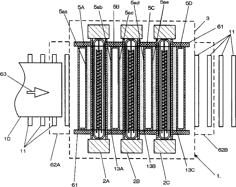
[0055] Figure 5 A third embodiment of the present invention is shown. In the third embodiment, a case is shown in which the flow rate of gas flowing into the first replacement space is different in each first replacement space formed corresponding to each excimer lamp. Figure 5 The illustrated excimer light irradiation device 1 is a view of the inside of the lamp housing of the excimer light irradiation device 1 in which three excimer lamps 2A, 2B, and 2C are arranged in parallel are viewed from above the device. Also, a conveyance path formed by arranging a plurality of roller belts 11 outside the excimer photoirradiation apparatus 1 and a state in which the substrate 10 is conveyed in the direction of the arrow 63 on the conveyance path are shown. The substrate 10 is carried in from the carrying port 62A of the excimer photoirradiation apparatus 1 and carried out from the carrying port 62B. Excimer lamps 2A, 2B, and 2C are arranged side by side between the transfer port ...


PUM


Abstract

The invention provides a quasimolecule light irradiating device. The cleaning can devices effectively clean the glass substrate used in a liquid crystal panel with quasimolecule lights and also can clean large-scale substrates without error. The invention is characterized in that a shell which is provided with a plurality of quasimolecule lamps is provided with a gas outlet tube which is used forspraying gases at least comprise inactive gases such as nitrogen; the invention is provide with a first replacing space which is formed by surrounding the gas outlet tube, the upper surface parts of quasimolecule lamps and the interval walls of the shell; and a second replacing space which is formed by surrounding the gas outlet tube, the lower surface parts of quasimolecule lamps and the transporting substrate; and the first replacing space is formed by spraying the inactive gases towards to the first replacing space from the gas outlet tube.

Description

technical field [0001] The present invention relates to an excimer light irradiation device, and more particularly to an excimer light irradiation device used for cleaning a substrate, etc., in the manufacturing process of a semiconductor or a liquid crystal substrate, and to produce an excimer light irradiation device having a characteristic structure of an atmosphere during cleaning . Background technique [0002] In recent manufacturing processes of semiconductors and liquid crystal substrates, dry cleaning using ultraviolet light is widely used as a method for removing contaminants such as organic compounds adhering to the surface of silicon wafers or glass substrates. In particular, in the method of cleaning with active oxygen such as ozone or vacuum ultraviolet rays emitted from an excimer lamp, various cleaning devices have been proposed, which can perform cleaning more efficiently and in a short time. As such a conventional technique, JP-A-2001-137800 and the like a...

Claims


Application Information

Patent Timeline
Patent Type & Authority Patents(China)
IPC IPC(8): B01J19/12B08B7/00G02F1/13G02F1/1333H01L21/304G21K5/00
CPCB08B7/0035H01L21/67034H01L21/67706
Inventor 远藤真一小柳博
Owner USHIO DENKI KK
Why Eureka
Try Eureka