Switching optical fibre laser on frequency

A fiber laser and frequency technology, applied in the direction of lasers, laser components, phonon exciters, etc., can solve problems such as difficult, unstable work, large volume, etc., and achieve high efficiency and multiple laser output wavelengths.

Inactive Publication Date: 2008-06-18
SOUTH CHINA UNIV OF TECH
View PDF0 Cites 7 Cited by
  • Summary
  • Abstract
  • Description
  • Claims
  • Application Information

AI Technical Summary

Problems solved by technology

This kind of gas laser has the disadvantages of large volume, short life and unstable work, and it w

Method used


Image

  • Switching optical fibre laser on frequency
  • Switching optical fibre laser on frequency

Examples


Embodiment 1

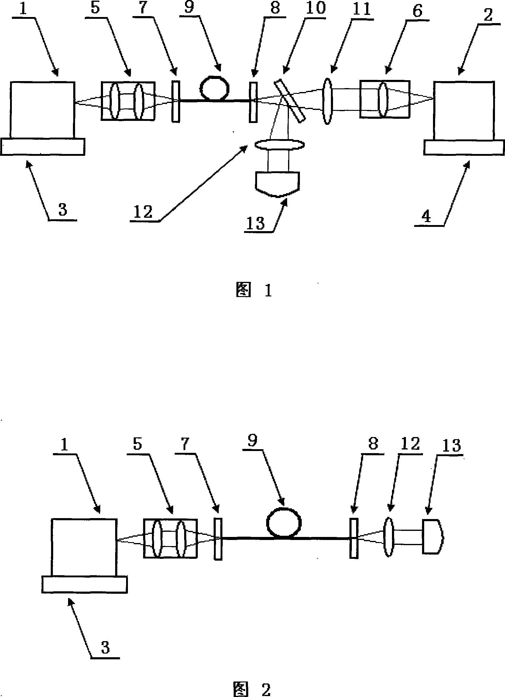
[0023] Fig. 1 is one of the structural schematic diagrams of the frequency up-conversion fiber laser of the present invention. Among them, the pump source 1 is a semiconductor laser with an output wavelength of 976nm. The pump laser is focused into a section of Er / Yb co-doped germanate glass double-clad optical fiber through the collimating and focusing lens group 5; the pump source 2 is A semiconductor laser with an output wavelength of 803nm, the pump laser passes through the collimating lens group 6, and then is focused into the optical fiber through the focusing lens 11. The focal length of the focusing lens 11 is 5 cm, so that the dichroic beam splitter 10 is as close as possible to the output coupling mirror 8 . The input coupling mirror 7 is a flat dichroic mirror with high transmission to the 976nm pump laser and high reflection to the 545nm signal laser. Transmitting and highly reflecting the output 545nm signal laser, the output coupling mirror 8 is a plano-concave ...

Embodiment 2

[0027] The present invention can also adopt the solution of unidirectional pumping, as shown in FIG. 2 . It includes: pumping source 1, temperature control system 3, collimating and focusing lens group 5, input coupling mirror 7, output coupling mirror 8, rare earth doped optical fiber 9, collimating mirror 12, and detection system 13. The relationship between the components is: the pumping source 1 stably outputs the pump laser light through the temperature control system 3, and after being focused by the collimating and focusing lens group 5, it is coupled into the rare earth-doped optical fiber 9 through the input coupling mirror 7. The input coupling The contact end faces of the mirror 7 and the rare-earth-doped optical fiber 9 should be close to each other, and the generated visible light (especially blue-green light) laser part passes through the output coupling mirror 8 and enters the detection system 13 after being collimated by the collimating mirror 12 .

[0028] Whe...

Embodiment 3

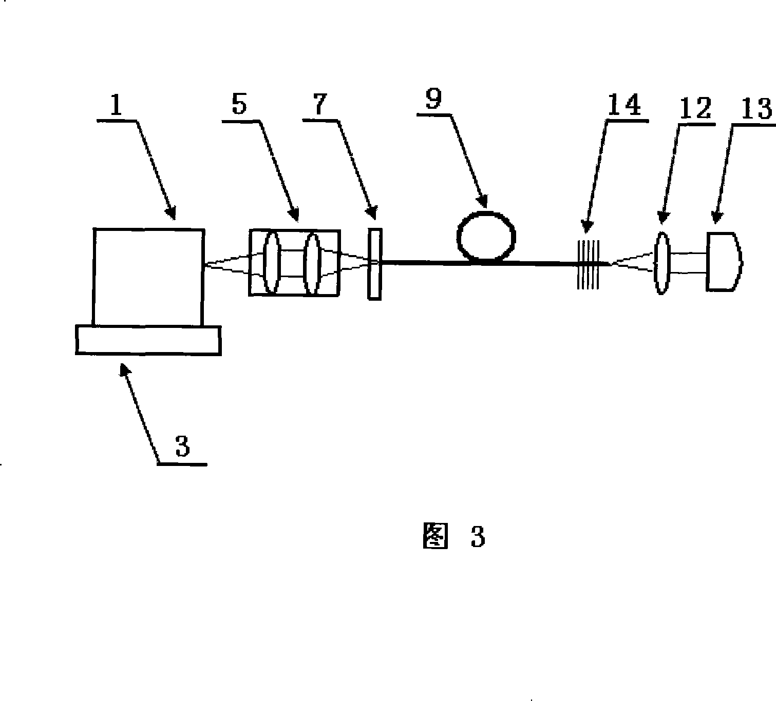
[0030] The present invention uses a fiber Bragg grating as a solution for the output coupling mirror, as shown in FIG. 3 . It includes: pumping source 1, temperature control system 3, collimating and focusing lens group 5, input coupling mirror 7, fiber Bragg grating 14, rare earth doped optical fiber 9, collimating mirror 12, and detection system 13. The relationship between the components is: the pumping source 1 stably outputs the pump laser light through the temperature control system 3, and after being focused by the collimating and focusing lens group 5, it is coupled into the rare earth-doped optical fiber 9 through the input coupling mirror 7. The input coupling The contact end faces of the mirror 7 and the rare-earth-doped optical fiber 9 should be close to each other, and the generated visible light (especially blue-green light) laser part passes through the fiber Bragg grating 14 and enters the detection system 13 after being collimated by the collimating mirror 12 ....


PUM


Abstract

The invention discloses a frequency up-conversion fiber laser, comprising a pumping source 1, a temperature control system 3, a collimation focusing lens group 5, an input coupling lens 7, an output coupling lens 8 and a rare earth mixed fiber 9; wherein, the pumping source 1 outputs stably a pumping laser through the temperature control system 3; the pumping laser is focalized through the collimation lens group 5, permeates the input coupling lens 7 and is coupled into the rare earth mixed fiber 9 to generate a frequency up-conversion laser part which is output through the output coupling lens 8; the input coupling lens 7 and/or the output coupling lens 8 of the frequency up-conversion fiber laser can be replaced by a fiber grating 14. Alternatively, a pumping source 2 and a dichroic beamsplitter 10 can be adopted on the other end surface of the fiber, so as to lead the dichroic beamsplitter 10 to form an angle of 45 DEG with an optical axis. The invention has the advantages of high laser efficiency, a plurality of wavelengths which are output by the laser, and being beneficial for the output of visible light (especially for blue green light) and laser with different wavelengths at the same time and for the miniaturization and integration of devices.

Description

technical field [0001] The invention relates to a fiber laser, in particular to a frequency up-conversion fiber laser. Background technique [0002] With the rapid development of technologies such as high-density data storage, three-dimensional display, submarine communication, optical fiber sensing, and laser medical treatment, there is an increasing need for high-efficiency, low-cost, and high-performance visible light short-wavelength laser sources, especially blue-green lasers. light source. [0003] There are mainly the following methods for blue-green solid-state lasers to obtain laser output: (1) directly using wide-bandgap semiconductor materials for direct excitation; (2) using nonlinear optical crystals for frequency doubling; (3) using rare earth ion doping Materials for upconversion luminescence. For semiconductor laser diodes (LD) in the visible band, there are still a series of technical problems, and the beam quality is not satisfactory, which is limited in ...

Claims


Application Information

Patent Timeline
IPC IPC(8): H01S3/067H01S3/094H01S3/16H01S3/08
Inventor 杨中民徐善辉江小平
Owner SOUTH CHINA UNIV OF TECH
Why Eureka
Try Eureka