
Method for manufacturing hydrodynamic bearing and rotating shaft

A technology of a dynamic pressure bearing and a manufacturing method, which is applied to sliding contact bearings, rotating bearings, bearings, etc., can solve problems such as difficulty in ensuring dimensional accuracy, narrow bearing hollow parts, and difficulty in improving product mass production and stability. , to achieve the effect of improving mass productivity and dimensional accuracy

Inactive Publication Date: 2008-06-25
FU ZHUN PRECISION IND SHENZHEN +1
View PDF1 Cites 22 Cited by
  • Summary
  • Abstract
  • Description
  • Claims
  • Application Information

AI Technical Summary

Problems solved by technology

However, due to the miniaturization trend of the bearing, the inner diameter of the bearing is relatively reduced, and the lines of the dynamic pressure groove are finer, and the hollow part of the bearing is narrow, so it is very difficult to form the dynamic pressure groove, and it is difficult to improve the product quality. Mass production and stability
[0005] Chinese Patent Announcement No. CN1721717A discloses a combined dynamic pressure bearing device and its manufacturing method. In this manufacturing method, each bearing block is manufactured and formed separately, and it is easy to cause assembly tolerance and concentricity problems when each bearing block is combined. , it is difficult to guarantee the dimensional accuracy

Method used


Image

  • Method for manufacturing hydrodynamic bearing and rotating shaft
  • Method for manufacturing hydrodynamic bearing and rotating shaft
  • Method for manufacturing hydrodynamic bearing and rotating shaft

Examples


Embodiment Construction

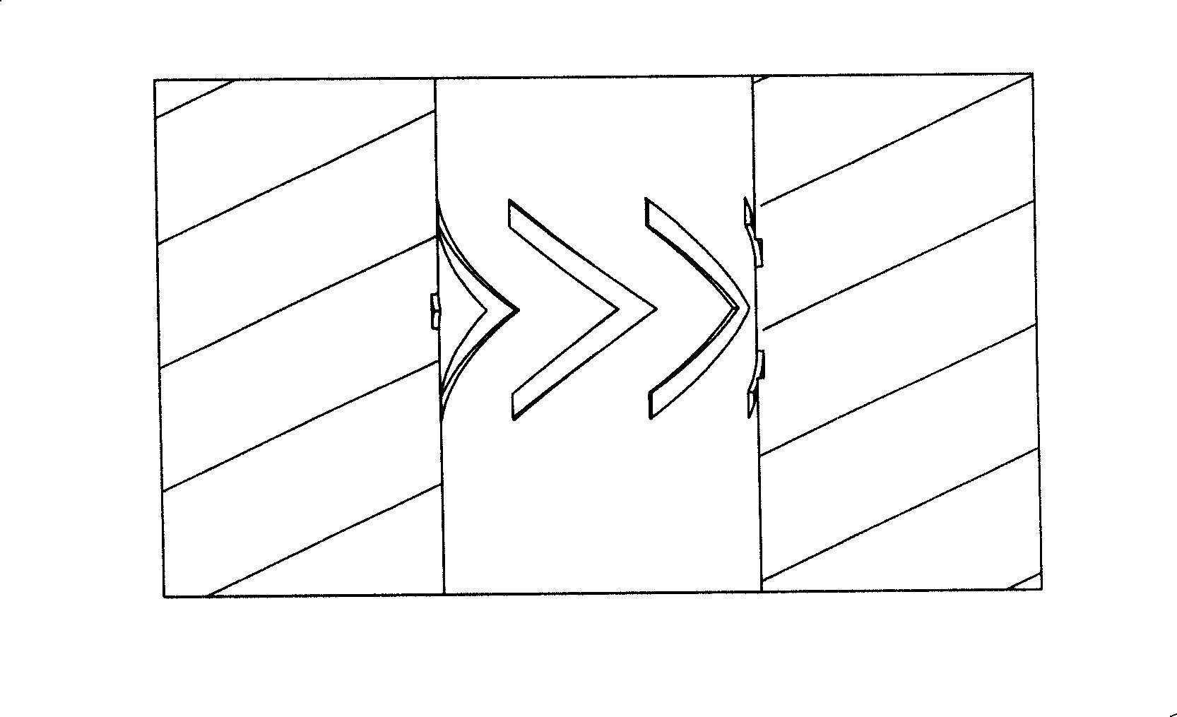
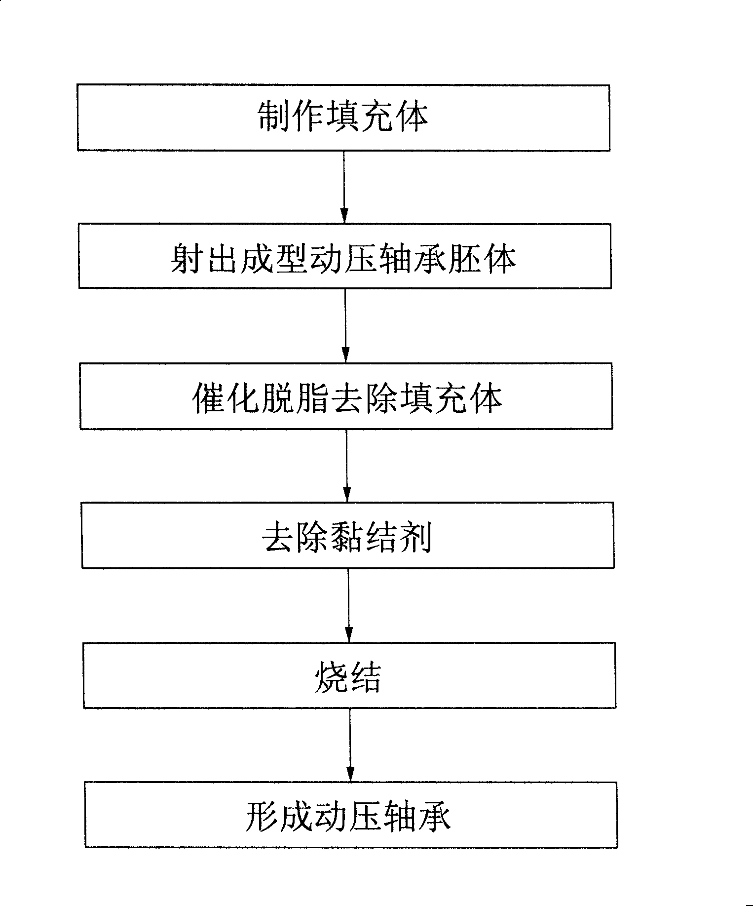
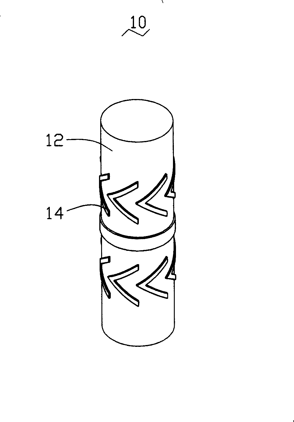
[0015] see Figure 2 to Figure 5 , the surface of the inner hole of the dynamic pressure bearing 30 according to an embodiment of the present invention is distributed with a number of "herringbone" shaped dynamic pressure grooves 34, and these dynamic pressure grooves 34 are used to generate a dynamic pressure effect. The manufacturing method of the dynamic pressure bearing 30 includes the following steps: firstly, a filling body 10 is provided, and the surface of the filling body 10 is provided with a plurality of protrusions 14; secondly, the filling body 10 is placed in a hollow bearing mold (not shown in the figure) ), and fill the metal powder or ceramic powder material into the hollow cavity of the bearing mold by injection molding to form the dynamic pressure bearing blank body 20; again, the filling body 10 is degreased by catalytic Removed from the dynamic pressure bearing blank 20, so that the inner wall surface of the dynamic pressure bearing blank 20 has just forme...


PUM

PropertyMeasurementUnit
water absorptionaaaaaaaaaa

Abstract

The invention provides a manufacturing method of dynamic pressure bearing, which comprises the following steps: an obturator is provided, the surface of the obturator is convexly provided with a plurality of protrusions; the obturator is arranged in the central position of a hollow bearing mould, and a hollow cavity in the bearing mould is filled with the mode of encapsulation molding to form an embryo of the dynamic pressure bearing; the obturator is removed from the embryo of the dynamic pressure bearing through the mode of catalytically degreasing; binder in the embryo of the dynamic pressure bearing is removed; the embryo of the dynamic pressure bearing is sintered; finally, the dynamic pressure bearing is formed. The dynamic pressure bearing integrally forms the dynamic pressure bearing and a dynamic pressure groove through the method of encapsulation molding, and removes micro-molecular gases which is decomposed from the obturator by using the method of catalytically degreasing, thereby preventing the embryo of dynamic pressure bearing from generating defects as deformation, bending or fracture, etc., improving the mass production capability and the dimensional precision of the dynamic pressure bearing. The invention also provides a manufacturing method of a dynamic pressure rotating shaft.

Description

technical field [0001] The invention relates to a bearing and a rotating shaft, in particular to a method for manufacturing the dynamic pressure bearing and the rotating shaft. Background technique [0002] At present, bearings are widely used in various equipment, especially dynamic pressure bearings are more commonly used in electronic devices, such as hard disk drives (HDD), compact disc drives (CD-ROM), digital video disc players (DVD), miniature discs Machine (MiniDisc), magneto-optical disk (MO) and cooling fans and other fields, the bearings of the motors in these devices are small in size, and the requirements for the rotation accuracy and life of the bearings are high. [0003] The dynamic pressure bearing forms a layer of fluid (gas or liquid) lubricating oil film in the tiny gap between the rotating shaft and the bearing. The lubricating fluid generates a dynamic pressure effect through the shear force of different cross-sectional areas, so that the dynamic pressu...

Claims


Application Information

Patent Timeline
Patent Type & Authority Applications(China)
IPC IPC(8): F16C33/14F16C33/04F16C3/02B28B1/24B28B7/34B28B7/28B22F5/00B22F3/115B22F3/10B22F3/24B29D31/00
CPCC04B35/638B28B7/342F16C17/02B22F2999/00C04B2235/945F16C17/026B28B1/24Y10T29/49639C04B2235/6022B22F3/225F16C2220/20C04B35/63488Y10T29/49636F16C33/14F16C2220/02F16C2220/48F16C2220/60F16C2223/30F16C2226/32B22F3/1291B22F3/1021B22F3/162
Inventor 侯春树
Owner FU ZHUN PRECISION IND SHENZHEN
Learn More