Polarizing plate and image display apparatus
A technology for polarizers and polarizers, applied in the field of image display devices, can solve problems such as damage to polarizers and non-uniformity, and achieve the effects of excellent optical properties and excellent appearance
- Summary
- Abstract
- Description
- Claims
- Application Information
AI Technical Summary
Problems solved by technology
Method used
Image
Examples
Embodiment 1
[0114] (Production Example 1: Production of Polarizer)
[0115] A polyvinyl alcohol film having a thickness of 80 μm was dyed in a 5% by weight iodine aqueous solution (weight ratio: iodine / potassium iodide=1 / 10). Then, the obtained polyvinyl alcohol film was immersed in an aqueous solution containing 3% by weight of boric acid and 2% by weight of potassium iodide. In addition, the polyvinyl alcohol film was stretched 6 times in an aqueous solution containing 4% by weight of boric acid and 3% by weight of potassium iodide, and then immersed in an aqueous solution of 5% by weight of potassium iodide. After that, the obtained polyvinyl alcohol film was dried in an oven at 40° C. for 3 minutes, whereby a polarizer having a thickness of 30 μm was obtained.
Embodiment 2
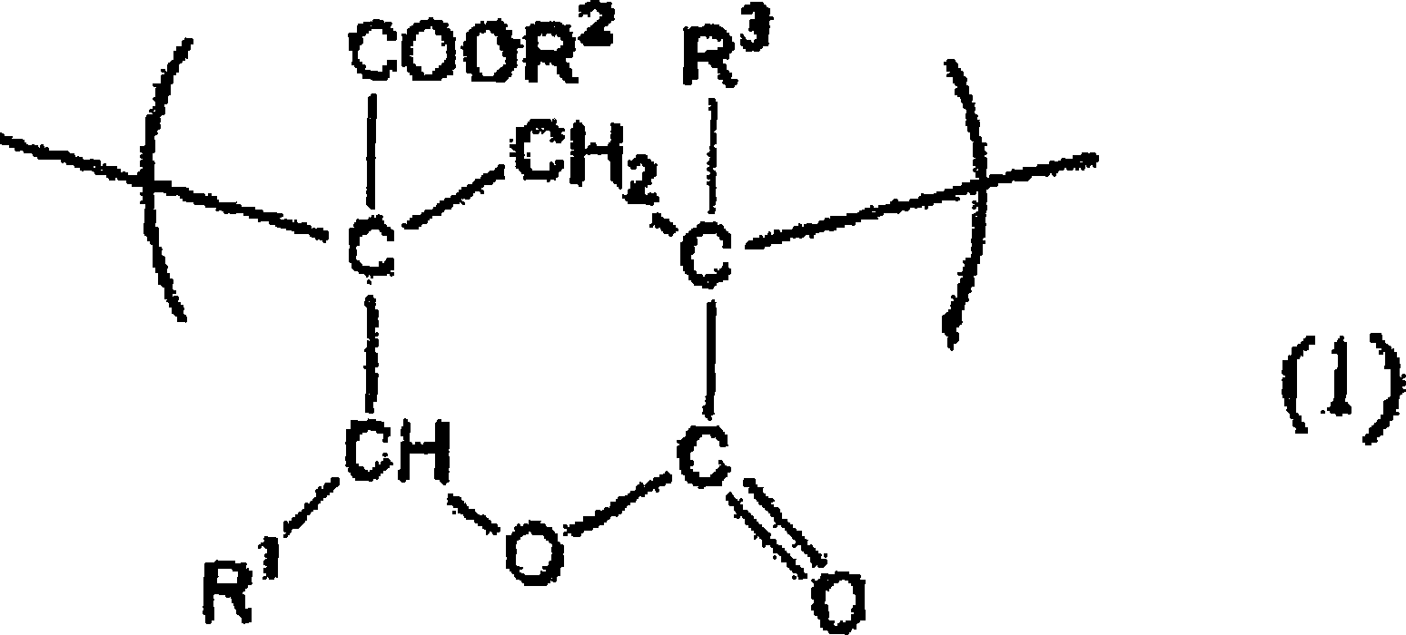
[0116] (Production Example 2: Production of an acrylic resin film containing a lactone ring having a lactone cyclization rate of 20%)
[0117] 8,000 g of methyl methacrylate (MMA), 2,000 g of 2-(hydroxymethyl)methyl acrylate (MHMA), 10,000 g of 4-methyl-2-pentanone (methyl isobutyl ketone, MIBK) and 5 g of n-dodecanemercaptan were charged into a 30 L reaction vessel equipped with a stirrer, a temperature sensor, a cooling pipe, and a nitrogen introduction pipe, and the temperature of the thus obtained mixture was raised to 105° C. , while passing nitrogen through the vessel, whereby the mixture was refluxed. At this time, 5.0 g of tert-butyl peroxyisopropyl carbonate (Kayacarbon Bic-75 (trade name), produced by Kayaku Akzo Corporation) was added as an initiator, and 10.0 g of tert-butyl peroxyisopropyl carbonate was added dropwise within 4 hours. Simultaneously with a solution of peroxyisopropyl carbonate and 230 g of MIBK, solution polymerization was carried out at reflux (abo...
Embodiment 3
[0122] (Production Example 3: Production of an acrylic resin film containing a lactone ring having a lactone cyclization rate of 25%)
[0123] Optical film (2) was obtained in the same manner as in Production Example 2 (lactone cyclization rate: 25%) except that 7,500 g of methyl methacrylate (MMA) and 2,500 g of 2-( Hydroxymethyl) acrylate (MHMA) was substituted for 8,000 g methyl methacrylate (MMA) and 2,000 g 2-(hydroxymethyl) acrylate (MHMA).
[0124] The pencil hardness of the optical film (2) was B.
PUM
| Property | Measurement | Unit |
|---|---|---|
| thickness | aaaaa | aaaaa |
| thickness | aaaaa | aaaaa |
| glass transition temperature | aaaaa | aaaaa |
Abstract
Description
Claims
Application Information
 - R&D
- Intellectual Property
- Life Sciences
- Materials
- Tech Scout
- Unparalleled Data Quality
- Higher Quality Content
- 60% Fewer Hallucinations
Browse by: Latest US Patents, China's latest patents, Technical Efficacy Thesaurus, Application Domain, Technology Topic, Popular Technical Reports.
© 2025 PatSnap. All rights reserved.Legal|Privacy policy|Modern Slavery Act Transparency Statement|Sitemap|About US| Contact US: help@patsnap.com


