
Photolithography detection pattern and photolithography edition territory

A technology for detecting patterns and lithography plates, which is used in microlithography exposure equipment, photo-plate making technology on pattern surfaces, optics, etc., can solve the problems of scrap wafers and low device yields, and achieve comprehensive and accurate detection results. effect of reproducibility and repeatability, avoiding wafer scrap or low device yield

Active Publication Date: 2008-06-25
SEMICON MFG INT (SHANGHAI) CORP +1
View PDF1 Cites 11 Cited by
  • Summary
  • Abstract
  • Description
  • Claims
  • Application Information

AI Technical Summary

Problems solved by technology

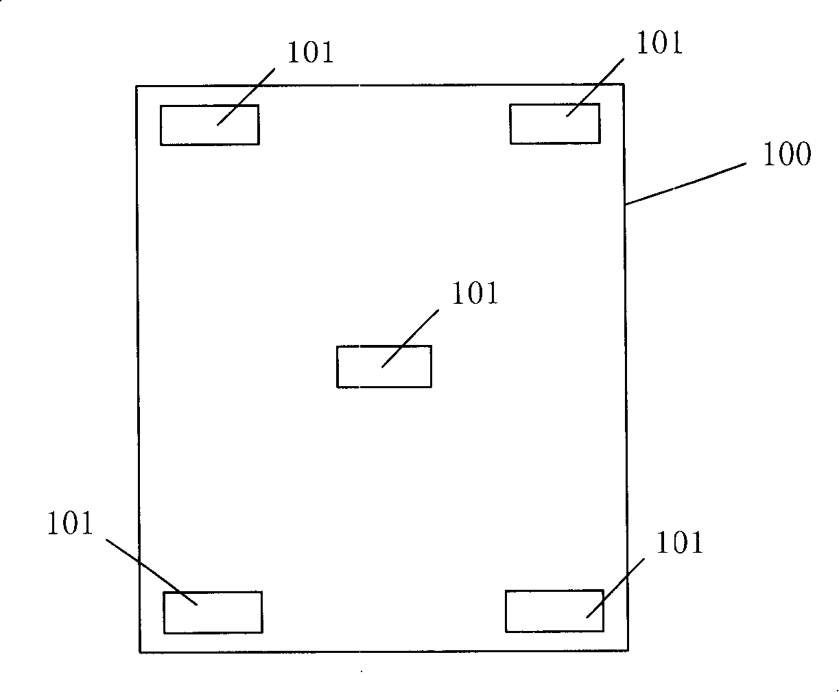
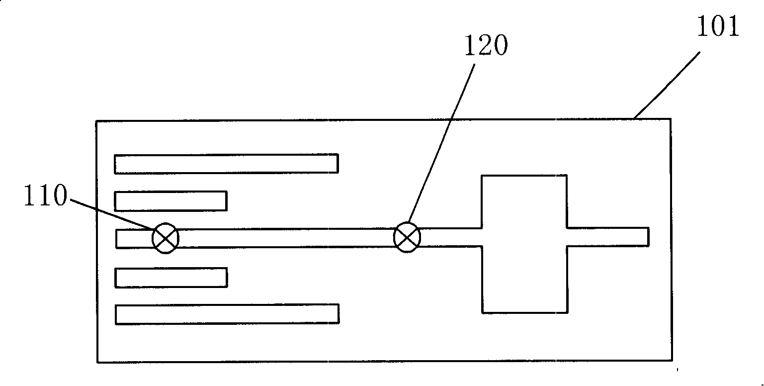
[0009] The invention provides a photolithographic detection pattern and a photolithography layout. The photolithography layout with the detection pattern can realize the monitoring of patterns of various densities, which improves the existing detection patterns that cannot fully detect photolithography. The problem of wafer scrapping or low device yield caused by the effect

Method used


Image

  • Photolithography detection pattern and photolithography edition territory
  • Photolithography detection pattern and photolithography edition territory
  • Photolithography detection pattern and photolithography edition territory

Examples


Embodiment Construction

[0031] In order to make the above-mentioned objects, features and advantages of the present invention more obvious and understandable, the specific embodiments of the present invention will be described in detail below with reference to the accompanying drawings.

[0032] The processing method of the present invention can be widely used in many applications, and can be made of many appropriate materials. The following is a preferred embodiment to illustrate, of course, the present invention is not limited to this specific embodiment. The general substitutions well-known to those of ordinary skill within are undoubtedly covered by the protection scope of the present invention.

[0033] Secondly, the present invention is described in detail using schematic diagrams. When describing the embodiments of the present invention, for convenience of explanation, the schematic diagrams will not be partially enlarged according to the general scale and should not be used as a limitation to the...


PUM

PropertyMeasurementUnit
widthaaaaaaaaaa

Abstract

The invention discloses a lithography detection graph and a lithography layout, wherein the detection graph comprises at least three sets of strip groups, the strip width and the distribution cycle inside each strip group are the same, the strip distribution cycles among the strip groups are different from one another; the layout with a plurality of detection graphs can realize the monitoring on the graphs of a plurality of sorts of concentration and improves the problem that the wafers are discarded or the finished product rate of the device is low because the prior detection graphs cannot detect the lithography effect completely.

Description

Technical field [0001] The present invention relates to the technical field of semiconductor manufacturing, in particular to a photolithography detection pattern and a photolithography layout. Background technique [0002] In the field of integrated circuit manufacturing, photolithography is used to transfer patterns from a photolithography mask containing circuit design information to a wafer. The photolithography mask (mask), also known as photolithography, mask or photomask, is a flat plate that is translucent to exposure light, and has at least one light-shielding plate on it. The geometric pattern can selectively block the light irradiated on the photoresist on the surface of the wafer, and finally form a corresponding pattern on the photoresist on the surface of the wafer. In semiconductor manufacturing, how to ensure that the designed pattern is accurately transferred to the semiconductor wafer is one of the key issues that must be paid attention to. [0003] However, whet...

Claims


Application Information

Patent Timeline
Patent Type & Authority Applications(China)
IPC IPC(8): G03F7/20G03F1/14G03F1/00G03F1/44
Inventor 李庆刚
Owner SEMICON MFG INT (SHANGHAI) CORP
Learn More