Broadband radio frequency front end of intermediate wave frequency band high dynamic range

A high dynamic range, RF front-end technology, applied in electrical components, transmission systems, etc., can solve problems such as small dynamic range, high RF front-end noise figure, and low image rejection

Inactive Publication Date: 2008-06-25
HARBIN ENG UNIV
View PDF0 Cites 17 Cited by
  • Summary
  • Abstract
  • Description
  • Claims
  • Application Information

AI Technical Summary

Problems solved by technology

[0005] The purpose of the present invention is to provide a high dynamic range broadband radio frequency front-end in the medium and short wave band, t

Method used


Image

  • Broadband radio frequency front end of intermediate wave frequency band high dynamic range
  • Broadband radio frequency front end of intermediate wave frequency band high dynamic range
  • Broadband radio frequency front end of intermediate wave frequency band high dynamic range

Examples


specific Embodiment approach 1

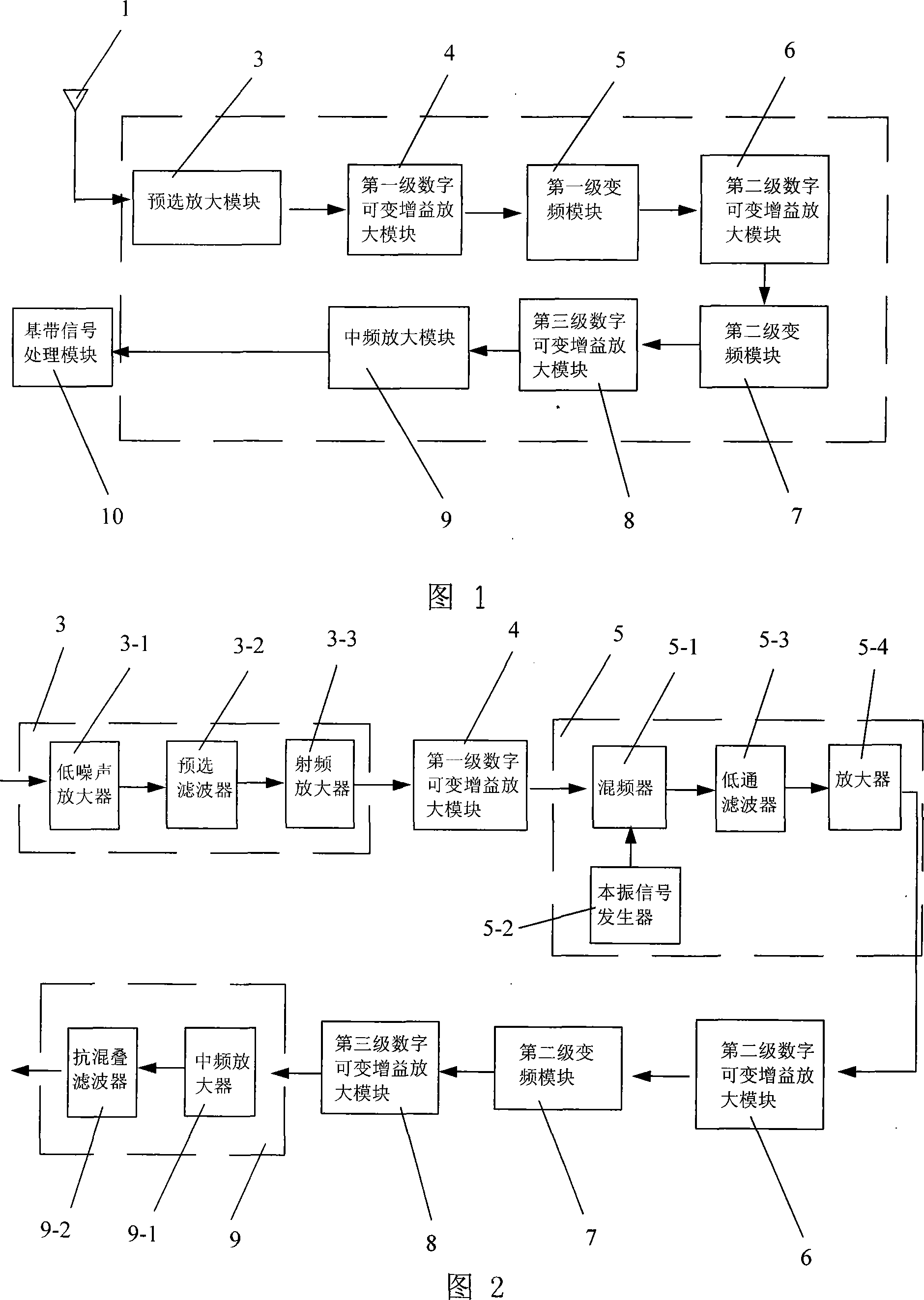
[0008] Specific Embodiment 1: The present embodiment will be specifically described below with reference to FIG. 1 . This embodiment consists of a preselected amplification module 3, a first-stage digital variable gain amplification module 4, a first-stage frequency conversion module 5, a second-stage digital variable gain amplification module 6, a second-stage frequency conversion module 7, and a third-stage digital variable gain amplifier module. The variable gain amplification module 8 and the intermediate frequency amplification module 9 are composed, the signal output end of the preselection amplification module 3 is connected to the signal input end of the first-stage digital variable gain amplification module 4, and the signal output end of the first-stage digital variable gain amplification module 4 Connect the signal input end of the first stage frequency conversion module 5, the signal output end of the first stage frequency conversion module 5 connects the signal inp...

specific Embodiment approach 2

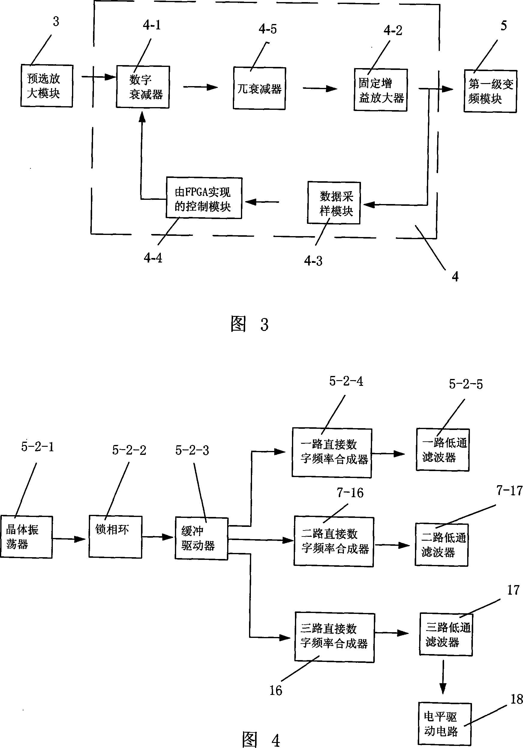
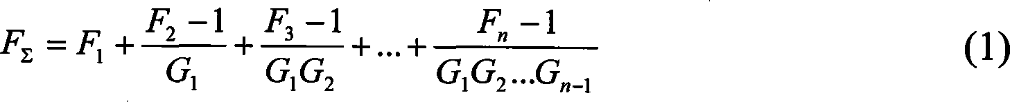
[0009] Specific Embodiment 2: The present embodiment will be specifically described below in conjunction with FIGS. 1 , 2 , 3 and 4 . The difference between this embodiment and the first embodiment is that the preselection amplification module 3 includes a low noise amplifier 3-1, a preselection filter 3-2 and a radio frequency amplifier 3-3, and the output end of the low noise amplifier 3-1 is connected with the preselection filter The input end of the preselection filter 3-2 and the output end of the preselection filter 3-2 are connected to the input end of the radio frequency amplifier 3-3. The preselection amplifier module 3 is the first stage where the radio frequency signal enters the front end, and plays the role of filtering out interference, reducing system noise figure, and amplifying weak signals. The gain of the preselected amplification module 3 is about 18dB. According to the formula for calculating the noise figure of the cascaded network, set the magnification...


PUM


Abstract

The invention provides a front end of broad band radio frequency in the medium-short wave frequency band high dynamic range, and relates to the front end of the broad band radio frequency in a medium-short wave frequency band spreading signal receiving system. The invention overcomes the shortcomings existing in the prior structure that the front end of the radio frequency has high noise coefficient, small dynamic range, and low image rejection. The front end of the radio frequency adopts a two-stage frequency conversion and low medium frequency outputting structure; a radio frequency signal enters into a medium-frequency baseband signal processing part after passing through a pre-amplification module, a frequency conversion module, a variable gain amplifier module, and a high-frequency amplifier module. The intermediate-frequency baseband processing part conducts digital demodulation under the drive of a clock signal. The variable gain amplifier module is realized by a digital method, and the dynamic requirement of the system can be ensured by three circuits of digital variable gain amplifier modules. Two circuits of local oscillation signals of the frequency conversion module and a clock signal provided to the digital baseband processing part are produced by a DDS plus PLL method. The PLL multiplies the frequency of a quartz oscillator outputted signal, the signal is inputted to three circuits of DDS after being driven by a buffer, and the signal output is realized.

Description

technical field [0001] The invention relates to a wideband radio frequency front end of a medium and short wave band spread spectrum signal receiving system. Background technique [0002] The medium and short wave frequency band generally refers to the frequency band of 0.5MHz-30MHz. The medium and short wave communication uses the ionosphere as the transmission medium, and the transmission distance can reach thousands of kilometers. Because medium and short wave communication has the characteristics of strong invulnerability and long transmission distance, it is widely used. Currently, medium and short wave frequency bands are not used by high dynamic range communication systems (such as mobile communication). The spread spectrum communication system refers to the communication system in which the spectrum of the information to be transmitted is expanded by a specific spread spectrum function to become a broadband signal, sent to the channel for transmission, and then comp...

Claims


Application Information

Patent Timeline
IPC IPC(8): H04B1/707H04B1/16H04B1/7093
Inventor 沈锋郝燕玲徐定杰王伟薛冰韦金辰黄平
Owner HARBIN ENG UNIV
Why Eureka
Try Eureka