Method and equipment for liquid-solid continuously separation for slurry state bed reactor

A reactor and slurry bed technology, which is applied in the field of liquid-solid continuous separation and equipment for slurry bed reactors, can solve the problems of complicated operation, complex equipment structure, and occupied reaction space, so as to improve the settlement efficiency and improve the Separation efficiency, the effect of high separation efficiency

Active Publication Date: 2008-07-02
CHINA PETROLEUM & CHEM CORP +1
View PDF6 Cites 24 Cited by
  • Summary
  • Abstract
  • Description
  • Claims
  • Application Information

AI Technical Summary

Problems solved by technology

Most of the area and space of the equipment are occupied by the settling device, and the production efficiency is low; because the diameter of the Fischer-Tropsch synthesis reactor is quite large, it is difficult for the magnetic field device to generate a uniform magnetic field in the reactor, the equipment is heavy, expensive, and It is impossible to demagnetize the magnetized catalyst to prevent the agglomeration of the magnetized catalyst and affect the normal operation of the reactor
[0008] WO 94 / 16807 discloses a method of using a filter assembly in a reactor to achieve liquid-solid separation, but once the catalyst particles block the filter assembly, the regeneration of the filter assembly is difficult, so it is not suitable for large-scale continuous production
[0009] CN1589957A discloses that a primary separation unit is set inside the reactor, a secondary separation unit is set outside the reactor to realize liquid-solid separation, and a recoil unit is set outside the reactor to realize the continuous operation of filtration, which not only takes up The reaction space in the reactor also leads to complex equipment structure and complicated operation

Method used


Image

  • Method and equipment for liquid-solid continuously separation for slurry state bed reactor
  • Method and equipment for liquid-solid continuously separation for slurry state bed reactor

Examples


Embodiment

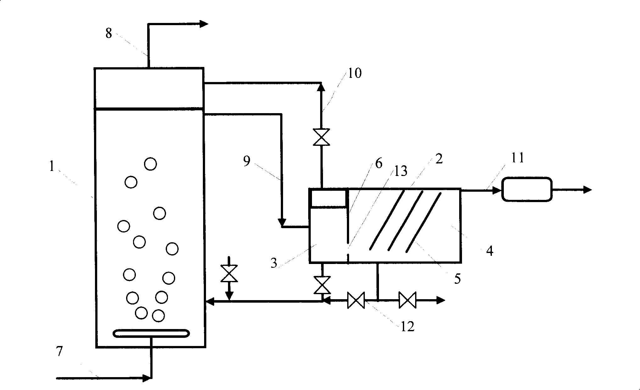
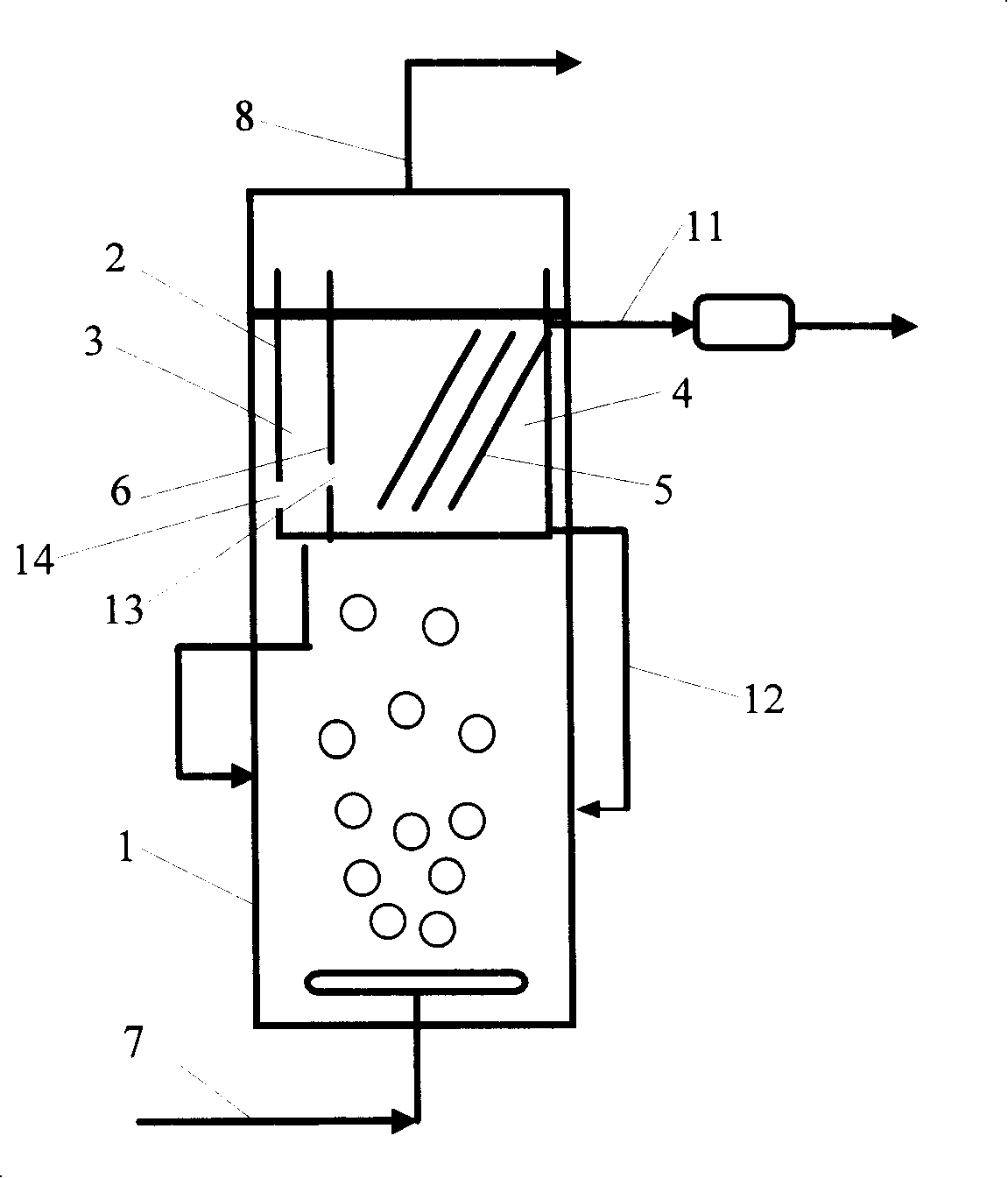
[0035] The process of continuous solid-liquid separation in the slurry bed reactor is shown in the attached figure 1As shown, the inclined plate settler adopts a group of parallel flat plates with a plate inclination angle of 50°, and the vertical distance between the plates is 0.05m. The suspended slurry discharged from the reactor is introduced into the pre-separator of the separation unit, the catalyst with larger particle size settles at the bottom of the preprocessor, the separated thicker slurry returns to the reactor to continue to participate in the reaction, and the separated gas returns to the upper part of the reactor , the rest of the suspended slurry flows into the inclined plate settler at the lower part of the preprocessor for further separation; the clear liquid separated in the inclined plate settler is a liquid product. Analysis by weighing method: the solid mass percentage in the clear liquid is less than 0.1%, the cutting particle size is 5 μm, and the sepa...


PUM

PropertyMeasurementUnit
angleaaaaaaaaaa
radiusaaaaaaaaaa
separationaaaaaaaaaa

Abstract

The invention discloses a method and a piece of equipment which are used for continuously separating liquid and solid of a serum-bed reactor. The contact reaction between materials and catalyst particles takes place in a serum-bed reactor, and suspension serum after the reaction is guided into a separation unit which comprises an inclined-plate settlement vessel and quickly separated into supernatant and concentrated serum in the inclined-plate settlement vessel, wherein, the concentrated serum returns to the reactor for continuing to participate in the reaction, and the supernatant flows upward into an upper part of the inclined-plate settlement vessel along gaps between the plates and is exhausted. The method provided by the invention implements the continuous separation and circular utilization of solid catalyst particles and liquid products in a smaller operation space and improves settlement efficiency. The equipment provided by the invention is applicable for separating suspension serum with smaller catalyst particles and larger liquid viscosity, occupies small space and has high separation efficiency.

Description

technical field [0001] The invention relates to a method and equipment for separating solid particles from liquid, more specifically, to a method and equipment for continuous separation of liquid and solid particles in a slurry bed reactor. Background technique [0002] The slurry bed reactor is a commonly used gas-liquid (slurry) contact reaction equipment with a very high liquid storage capacity. For the catalytic reaction process with large reaction heat, the use of slurry bed reactor can effectively remove the reaction heat, realize the isothermal operation of the reactor, and ensure the normal operation of the reactor, so it has been widely used in today's chemical process. [0003] In order to eliminate the influence of diffusion in a slurry bed reactor, catalysts with tens of microns or even finer particles are generally used. How to effectively realize liquid-solid separation after the reaction has become a key technology in the process of using a slurry bed reaction...

Claims


Application Information

Patent Timeline
Patent Type & Authority Applications(China)
IPC IPC(8): B01J8/22B01D21/02C10G2/00
Inventor 张占柱胡立峰唐晓津王少兵侯栓弟毛俊义渠红亮
Owner CHINA PETROLEUM & CHEM CORP
Why Eureka
Try Eureka