Laminate, liquid crystal panel, and liquid crystal display apparatus
A technology of laminates and liquid crystal panels, applied in static indicators, optics, instruments, etc., can solve the problems of reduced contrast, display unevenness, and increased display color changes, and achieve the effect of reducing thickness changes.
- Summary
- Abstract
- Description
- Claims
- Application Information
AI Technical Summary
Problems solved by technology
Method used
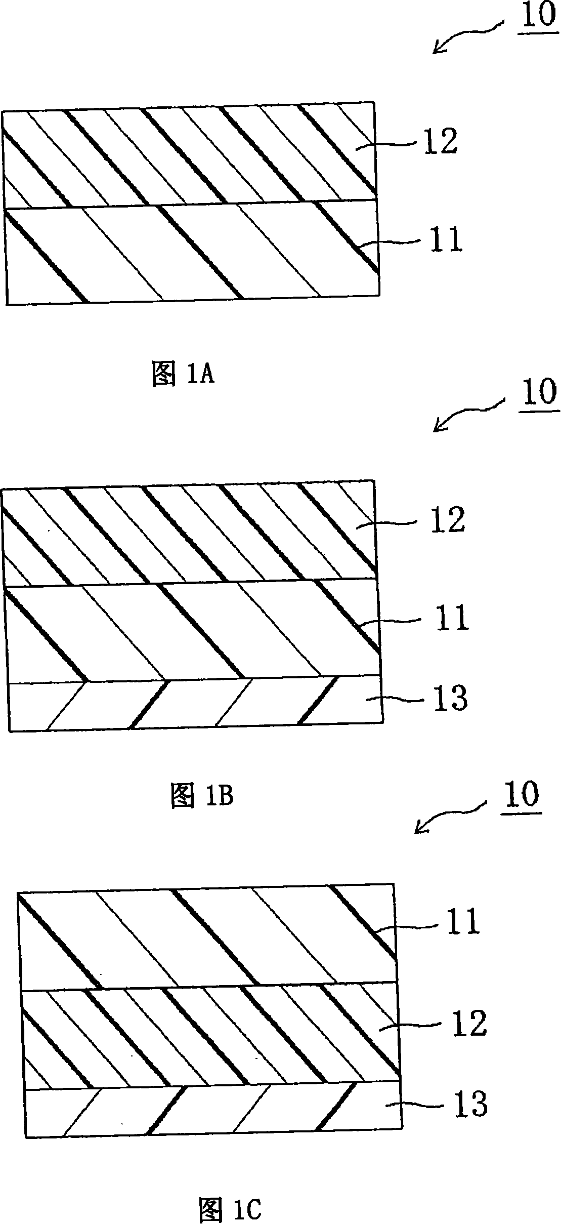
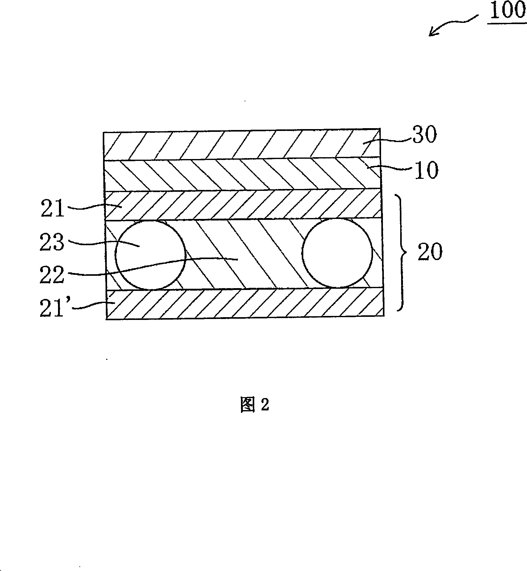
Image

Examples
Embodiment 1
[0142] 1. Preparation of Coating Solution
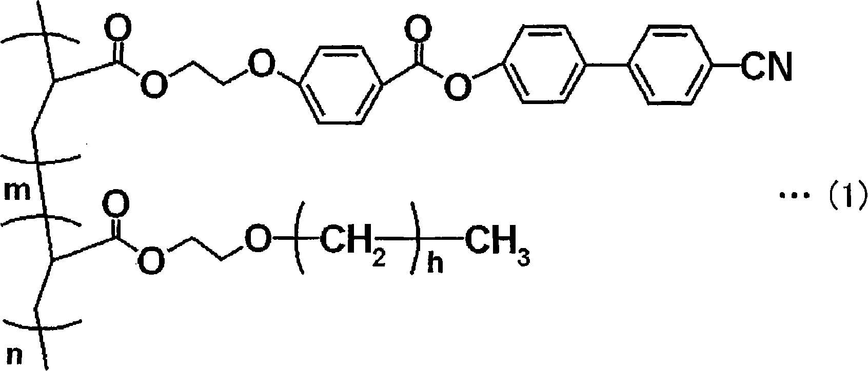
[0143] The following were mixed in the mixing ratios described in Table 1 to prepare a liquid crystal composition: a liquid crystal polymer represented by the following formula (3) (weight-average molecular weight: 5,000); a commercially available liquid crystal compound ("PaliocolorLC242" (commercial name), produced by BASF), which has a phenylbenzoate group as a mesogenic ligand and has two polymerizable functional groups in the molecular structure; a photopolymerization initiator ("IRGACURE127" (trade name) produced by produced by Ciba Specialty Chemicals Inc.); and a leveling agent (acrylate polymer (block oligomer of butyl acrylate·ethyl acrylate in a molar ratio of 50:50, weight average molecular weight: 16,000)). The obtained liquid crystal composition was mixed with cyclopentanone under shaking at 40° C. for 30 minutes to dissolve the cyclopentanone therein, thereby obtaining a coating solution.
[0144]
[0145] 2. Prepa...
reference example 1
[0162] Using an intermittent corona treatment device ("CORONA GENERATOR CT-0212" (trade name), manufactured by KASUGA DENKI Co. Ltd), the birefringent layer side of the laminate obtained in Example 1, that is, the side facing the base The side opposite to the material side, at 116W / m 2 · Minutes of corona treatment. The contact angle of the treated birefringent layer to pure water was 46°, so it was confirmed that the treated birefringent layer had satisfactory wettability. Similarly, when the side opposite to the substrate side facing the birefringent layer of the laminate obtained in Comparative Example 2 was subjected to corona treatment, the contact angle of the birefringent layer with respect to pure water was 57°. It is believed that the reason for the satisfactory wettability of the laminate obtained in Example 1 is that the non-siloxane-based position of the acrylate polymer (for example, the butyl group of butyl acrylate) in the birefringent layer A coating film of ...
Embodiment 2
[0164] By attaching a polarizing plate (“SIG1423” (trade name), manufactured by Nitto Denko Corporation) to the substrate side of the laminate obtained in Example 1 via an acrylic pressure-sensitive adhesive (thickness: 20 μm), obtained Laminates with polarizers. At this time, the polarizing plate was attached to the laminate such that the absorption axis of the polarizer of the polarizing plate and the slow axis of the base material as a positive A plate were perpendicular to each other. Then, the polarizing plate placed on the backlight side of the liquid crystal cell included in a liquid crystal television ("W37L-H9000" (trade name), manufactured by Hitachi Ltd.) was removed. The above laminate with a polarizer was attached to a liquid crystal cell via an acrylic pressure-sensitive adhesive (thickness: 20 μm) in place of the removed polarizing plate so that the birefringent layer was opposed to the liquid crystal cell, thereby preparing a liquid crystal display device. At ...
PUM
| Property | Measurement | Unit |
|---|---|---|
| water contact angle | aaaaa | aaaaa |
| thickness | aaaaa | aaaaa |
| thickness | aaaaa | aaaaa |
Abstract
Description
Claims
Application Information
 - R&D
- Intellectual Property
- Life Sciences
- Materials
- Tech Scout
- Unparalleled Data Quality
- Higher Quality Content
- 60% Fewer Hallucinations
Browse by: Latest US Patents, China's latest patents, Technical Efficacy Thesaurus, Application Domain, Technology Topic, Popular Technical Reports.
© 2025 PatSnap. All rights reserved.Legal|Privacy policy|Modern Slavery Act Transparency Statement|Sitemap|About US| Contact US: help@patsnap.com