Precision shaping molds separating group processing method

A technology of precision molding, disassembly and combination, applied in the direction of casting mold composition, casting molding equipment, metal processing equipment, etc., can solve the problems of failing to meet product design requirements, inaccurate sliding positioning, splashing of high-temperature liquid, etc., and achieve low cost , easy processing, and fully qualified effect

Inactive Publication Date: 2008-07-09
CHANGAN AUTOMOBILE (GRP) CO LTD
View PDF0 Cites 16 Cited by
  • Summary
  • Abstract
  • Description
  • Claims
  • Application Information

AI Technical Summary

Problems solved by technology

[0002] The dynamic mold core is the key part of the cavity mold, which directly determines the quality and performance of the molding (injection molding or die-casting) product. For the normal ejection of the product and the convenience of the structure, many cavity molds are designed with an inlay type Combination core structure, especially for rotary molding parts, it is composed of several identical cores. The shape of the moving core is tapered, which acts as a sliding fit to ensure that the mold can be released normally. The inner hole is the product requirement. For the shape part, the accuracy of the inside and outside dimensions of the mold, and coaxiality are all required to be within φ0.015mm. At present, this type of mold is first processed by the dynamic model core, and then the core is divided into several parts by using a precision wire cutting machine tool. parts, and combine the divided parts, but since the diameter of the copper wire of the precision wire cutting machine is at least φ0.1mm, when the combined core is divided and reassembled, due to the influence of the gap, the inner and outer circles of the mold cavity will be It is no longer a complete circle, so the sliding positioning of the mold is inaccurate during use, and when the product is formed, the product is not a complete circle, with large flashes and burrs, and it is easy to cause high-temperature liquid (plastic, aluminum water) to splash, causing A great potential safety hazard, completely failing to meet the product design requirements

Method used


Image

  • Precision shaping molds separating group processing method

Examples


Embodiment Construction

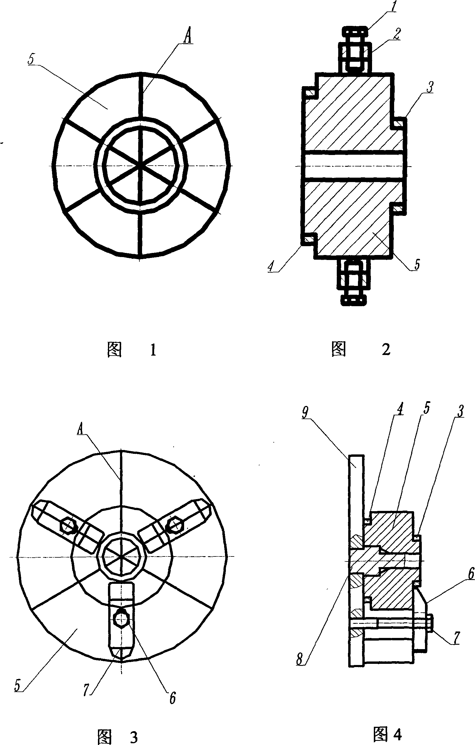
[0012] In Figure 1, when the six parts of the moving core 5 are reassembled, they are in a loose state and cannot be positioned correctly. When assembling, it is necessary to check the degree of bonding at the joint surface A of the two adjacent cores to ensure that the surface and surface Between more than 90% closeness;

[0013] In Figure 2, fix the moving model core 5 with hoop 2 and six M12 fastening screws 1, adjust the position of the M12 fastening screws 1, and try to ensure that the force is even, so that the radial position of the moving model core 5 is roughly consistent, and the moving model After the core 5 is fixed, it is clamped on a lathe, and the small-end positioning device 3 and the large-end positioning device 4 are processed. At this time, under the action of the small-end positioning device 3 and the large-end positioning device 4, the moving model core 5 is locked. When the hoop 2 is taken off, each component of the moving model core 5 can be firmly conne...


PUM


Abstract

The invention relates to a splitting and assembling processing method for a fine forming die which leads about 30mm of a movable mould core blank and utilizes a linear cutting processing to divide into a plurality of equal parts, codes running numbers according to sequence and carries through plane furbishing and polishing processing on a cutting parting surface; then utilizes the radial actions of an anchor ear and trip bolt to fix the movable mould core; clamps and turns the locating devices at two ends and then utilizes a fine jig mill to process a datum hole; then utilizes a self-turning mode and adopts the modes that a floral disc and a mandrel are tightly cooperated and the mandrel is cooperated with the datum hole of the movable mould core in small clearance to carry through fine forming processing on the inner shape and outer taper of a product. The die forming product processed by the method has the advantages of large extent improving on the surface quality and dimension precision, completely qualified quality, no security hidden troubles, convenient processing. The processing equipment used has the advantages of simple structure and lower cost.

Description

technical field [0001] The invention relates to a processing method specially used for precision forming moulds, in particular to a processing method for precision forming molds of rotary parts with an inlaid combined core structure. It is mainly used for processing molds with inlaid combined core structure and precision molding of rotary parts. Background technique [0002] The dynamic mold core is the key part of the cavity mold, which directly determines the quality and performance of the molding (injection molding or die-casting) product. For the normal ejection of the product and the convenience of the structure, many cavity molds are designed with an inlay type Combination core structure, especially for rotary molding parts, it is composed of several identical cores. The shape of the moving core is tapered, which acts as a sliding fit to ensure that the mold can be released normally. The inner hole is the product requirement. For the shape part, the accuracy of the in...

Claims


Application Information

Patent Timeline
Patent Type & Authority Applications(China)
IPC IPC(8): B22C9/10B22D17/22B29C33/76
Inventor 陈勇韩小斌
Owner CHANGAN AUTOMOBILE (GRP) CO LTD
Why Eureka
Try Eureka