Cooling fan control device and method

A cooling fan and control device technology, which is applied in the direction of coolant flow control, power plant cooling combination arrangement, pump control, etc., can solve the problems of reduced work efficiency, increased energy consumption, poor cooling effect, etc., and achieve improved operation Efficiency, work efficiency improvement, strong robustness effect

Active Publication Date: 2008-07-09
GUANGXI DAHUA DESHENG THERMAL MANAGEMENT SCI TECH
View PDF0 Cites 34 Cited by
  • Summary
  • Abstract
  • Description
  • Claims
  • Application Information

AI Technical Summary

Problems solved by technology

In the traditional cooling system, the cooling fan is usually installed on the engine. The change of the fan speed is corresponding to the change of the engine speed. The cooling effect is directly related to the engine speed. Therefore, the cooling system cannot meet all the working conditions of the system. Heat exchange requirements often cause overheating or overcooling of various system equipment that generates heat and needs to be cooled, such as engines of vehicles and construction machinery, hydraulic operating systems, hydraulic drive systems, and booster systems
Especially when t

Method used


Image

  • Cooling fan control device and method
  • Cooling fan control device and method
  • Cooling fan control device and method

Examples


Embodiment 1

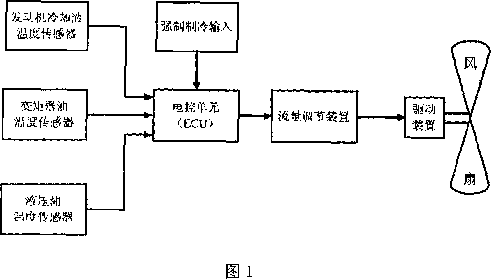
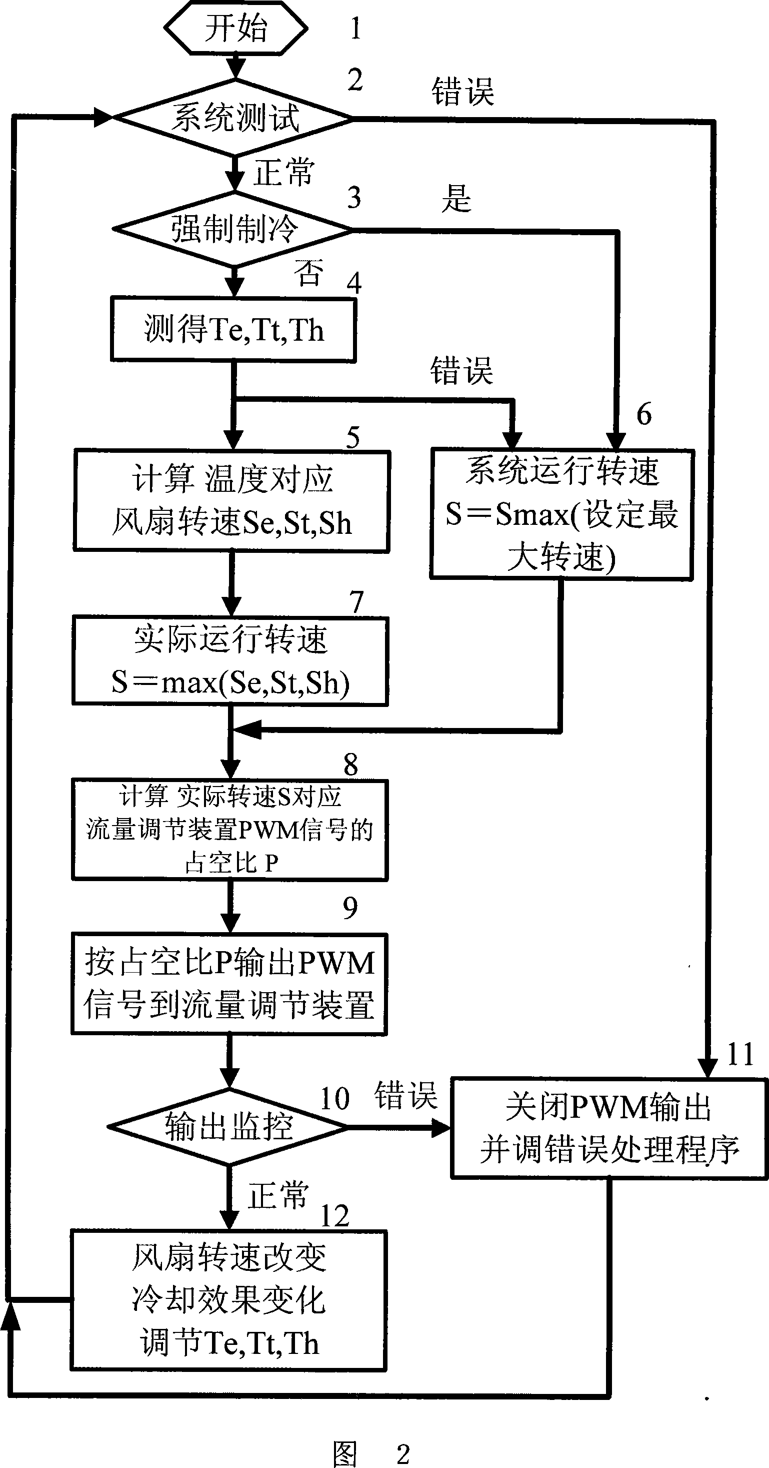
[0045] The bulldozer adopts a cooling fan control device of the present invention. Through the above-mentioned corresponding control method, by changing the speed of the cooling fan, the air volume through the cooling system is changed, and the cooling effect is changed, so that each cooling working medium maintains Within the normal range.

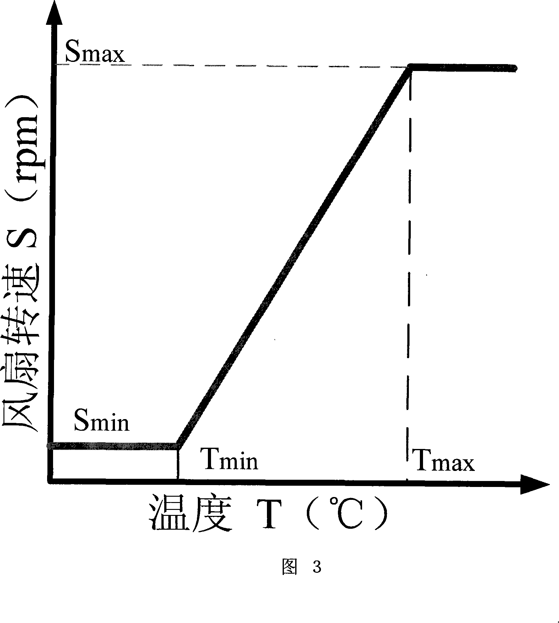
[0046] In the cooling fan control device, the electronic control unit receives the engine cooler temperature signal, the torque converter oil temperature signal and the hydraulic oil temperature signal collected by the temperature sensor, and according to the corresponding relationship between the temperature and speed set by the system, according to the engine cooler temperature Find the corresponding speed Se according to the relationship between the fan speed and the torque converter oil temperature and the fan speed; Find the corresponding speed Sh according to the relationship between the hydraulic oil temperature and the fan speed; and ...


PUM


Abstract

The invention provides a cooling fan control device, which comprises an engine coolant temperature probe, a torque converter oil temperature sensor, a hydraulic oil temperature sensor, an electric control unit, a forced cooling switching input, a flow regulator, a driving device and a fan. A monitoring sensor and a setting amount signal input are connected with the input end of the electric control unit. The output port of the electric control unit is connected with the flow regulator. The flow regulator is connected with the driving device. The driving device is connected with the fan. The invention provides a control algorithm of the device. According to the method, relevant system signal or other incoming signal is collected and processed; the control signal is output and acts on the flow regulator; the driving power output to the driving device is regulated through changing the duty ratio of the output pulse-width signal, thus regulating the rotation speed of the fan. The system is effectively ensured to work within the optimal temperature range all along; the service life of the system or components is improved; energy consumption is reduced; work efficiency is improved; and noise resulting from the fan is reduced.

Description

Technical field [0001] The invention relates to the field of vehicle fan control, in particular to a cooling fan control device and a control method thereof for adjusting the rotation speed of the cooling fan by changing the driving capability of the cooling fan. Background technique [0002] Vehicles and construction machinery will generate a lot of heat during their work. Due to changes in the working environment and working conditions, the heat production will also change accordingly. In order to maintain the normal operation of the equipment, various coolers or heat exchangers are usually used, and the heat is dissipated into the environment by forced cooling by a cooling fan. So as to keep the devices within the working range of normal temperature. In traditional cooling systems, the cooling fan is often installed on the engine, and the change of the fan speed is correspondingly changed by the change of the engine speed. The cooling effect is directly related to the engine s...

Claims


Application Information

Patent Timeline
IPC IPC(8): F04D27/00B60K11/06F01P7/04
Inventor 李毅刘景平
Owner GUANGXI DAHUA DESHENG THERMAL MANAGEMENT SCI TECH
Why Eureka
Try Eureka