Tunnel chamber for drying

A drying room and tunnel-type technology, which is applied in local agitation dryers, static material dryers, drying, etc., can solve the problems that are not conducive to the evaporation and drying of materials, the inability of continuous in and out of materials, and the decline in material quality. Drying time, shortened drying time, and high production efficiency

Inactive Publication Date: 2008-07-09
烟台一山机械有限公司
View PDF0 Cites 7 Cited by
  • Summary
  • Abstract
  • Description
  • Claims
  • Application Information

AI Technical Summary

Problems solved by technology

[0002] At present, the tunnel-type drying chambers used in the market generally include a drying chamber and a heater. After the air is heated, it exchanges temperature and humidity with the materials in the drying chamber. The high-temperature dry air absorbs the moisture of the materials and then cools down, and the humidity increases. After contacting the material in a cycle, it is directly discharged into the atmosphere, and the material is continuously in and out. Since the circulated air is directly discharged into the atmosphere, the heat loss is relatively large.
There are also some tunnel-type drying rooms on the market that also use a heater. The air in the drying room is heated by circulation. The air that has been heated many times contacts the material many times. The drying capacity decreases after the amount increases, so this kind of drying room can only use one-time feeding, first cycle heating, and then use the second-stage drying method of replenishing new air and discharging high-humidity air (that is, heating period and exhaust air drying period). The disadvantage of this drying room is that the material cannot be continuously fed in and out, the work efficiency is low, and the heat loss during the exhaust drying period is large.
When the above two kinds of equipment are in normal operation, the drying chamber is in a slightly positive pressure state, which is not conducive to the evaporation and drying of the material moisture. The drying time is long, and the quality of the material decreases with the extension of the drying time.

Method used


Image

  • Tunnel chamber for drying

Examples


Embodiment Construction

[0011] The present invention will be further described in detail below in conjunction with specific implementation examples.

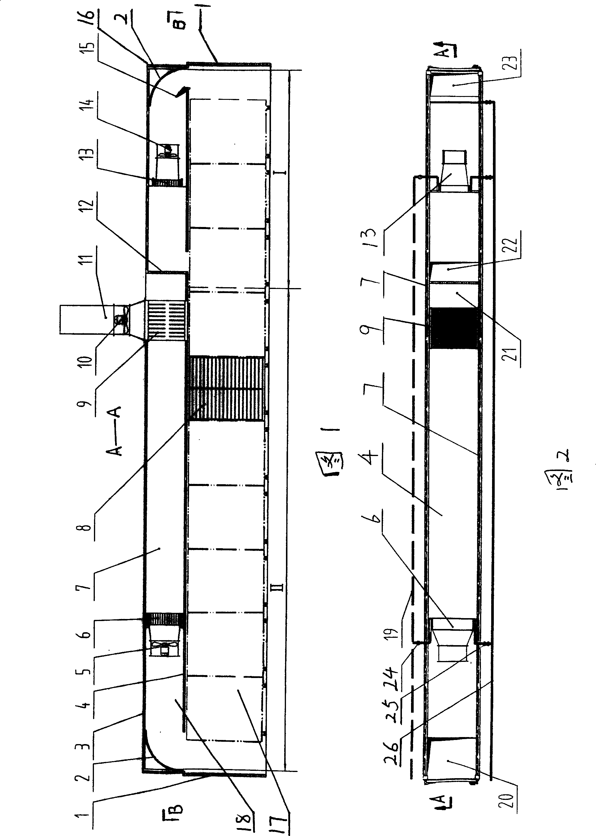
[0012] The present invention is in the drying chamber 16 that is made up of drying chamber door 1, drying chamber top board 3, drying chamber side plate 7, and middle board 4 is housed, and middle board 4 divides drying chamber 16 into drying chamber 17 (middle board 4 and the ground) and the air duct 18 (between the top plate 3 and the middle plate 4 of the drying chamber). A partition 12 is installed in the air duct 18, and the partition 12 divides the air duct 18 into two parts, front and rear. An air preheater 9, a main heat exchanger 6 and a main fan 5 are provided, and an auxiliary heat exchanger 13, an auxiliary fan 14 and a steam nozzle 15 are arranged in the rear air duct. The middle plate is provided with a dry hot air outlet 20, a heating return air outlet 22, and a heating air outlet 23. The partition 12 is located in the air duct 18 close ...


PUM


Abstract

The invention discloses a tunnel type drying chamber, which comprises an oven-drying room (16), a material carriage (8), a primary heat exchanger (6) and an air discharge tube (11). The invention is characterized in that a middle plate (4) is disposed inside the oven-drying room (16) and divides the drying room (16) into a drying room (17) and an air duct (18), a dry hot air port (20), a heating return air port (22) and a heating air outlet port (23) are disposed on the middle plate (4), a partitioning plate (12) is disposed in the air duct (18) close to the heating return air port (22) and divides the air duct (18) into a front air duct and a rear air duct, an air preheater (9), the primary heat exchanger (6) and a primary air blower (5) are disposed inside the front air duct, a secondary heat exchanger (13), a secondary air blower (14) and a steam nozzle (15) are disposed inside the rear air duct, a fresh air inlet port (21) is disposed at the front upper side of the partitioning plate (12), the air preheater (9) is disposed in the front of the fresh air inlet port (21), a moisture-removal blower (10) is disposed on the air preheater (9), and the air discharge tube (11) is disposed on the moisture-removal blower (10). The invention has the advantages of high drying efficiency and low energy consumption.

Description

technical field [0001] The invention relates to a drying device for removing moisture from wet materials, in particular to a tunnel-type drying chamber used in food drying. Background technique [0002] At present, the tunnel-type drying chambers used in the market generally include a drying chamber and a heater. After the air is heated, it exchanges temperature and humidity with the materials in the drying chamber. The high-temperature dry air absorbs the moisture of the materials and then cools down, and the humidity increases. After contacting the material in a cycle, it is directly discharged into the atmosphere, and the material is continuously fed in and out. Since the circulated air is directly discharged into the atmosphere, the heat loss is relatively large. There are also some tunnel-type drying rooms on the market that also use a heater. The air in the drying room is heated by circulation. The air that has been heated many times contacts the material many times. ...

Claims


Application Information

Patent Timeline
Patent Type & Authority Applications(China)
IPC IPC(8): F26B9/06F26B9/02
Inventor 陈耀强陈力铭吕序鑫赵少华李冉
Owner 烟台一山机械有限公司
Why Eureka
Try Eureka