
Polarization insensitive array wave-guide grating

An arrayed waveguide grating, polarization-insensitive technology, applied in the coupling of optical waveguides, etc., can solve the problems of unsuitable silicon nanowire arrayed waveguide gratings, etc., and achieve the effect of convenient design and simple structure

Inactive Publication Date: 2008-07-09
ZHEJIANG UNIV
View PDF0 Cites 7 Cited by
  • Summary
  • Abstract
  • Description
  • Claims
  • Application Information

AI Technical Summary

Problems solved by technology

However, the traditional polarization compensation technology can only eliminate the polarization dependence of the central wavelength, and is not suitable for silicon nanowire arrayed waveguide gratings.

Method used


Image

  • Polarization insensitive array wave-guide grating

Examples


Embodiment Construction

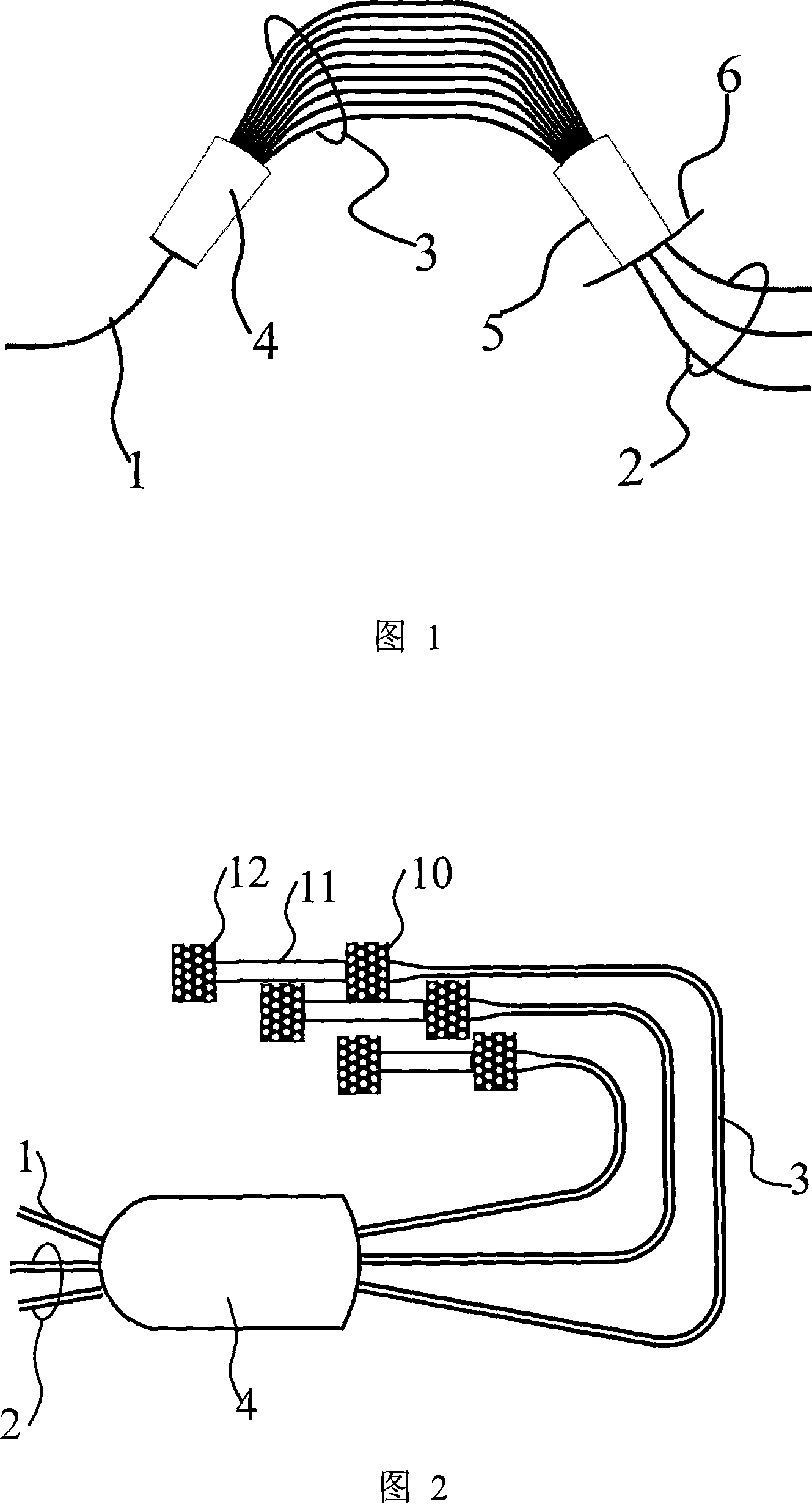
[0013] Referring to Fig. 2, the polarization-insensitive arrayed waveguide grating of the present invention comprises an input waveguide 1, an output waveguide 2, a slab waveguide 4 and several arrayed waveguides 3, the input waveguide 1 and the output waveguide 2 are located on the same side of the slab waveguide 4, and The slab waveguides 4 are connected, and the other side of the slab waveguides 4 is connected to one end of each arrayed waveguide 3, and there is an optical path difference ΔL between adjacent arrayed waveguides 1 , the other end of each arrayed waveguide is sequentially connected to the polarizing beam splitter 10 and the mirror 12, there is a connecting waveguide 11 between the polarizing beam splitter 10 and the reflecting mirror 12, and there is an optical path difference ΔL between adjacent connecting waveguides 11 2 .

[0014] A specific embodiment is given below.

[0015] In this example, the refractive indices of the core layer, lower cladding layer,...


PUM


Abstract

The invention discloses a polarization insensitive array waveguide grating, which comprises an input waveguide, an output waveguide, a planar waveguide and a plurality of array waveguides, wherein the input waveguide and the output waveguide are positioned on the same side of the planar waveguide and are connected with the planar waveguide; the other side of the planar waveguide is connected with one end of each array waveguide; adjacent array waveguides have an optical path difference DeltaL1; the other ends of the array waveguides are sequentially connected with a polarization beam splitter and a reflector; connection waveguides are arranged between the polarization beam splitter and the reflector; and adjacent connection waveguides has an optical path difference DeltaL2. Due to the introduction of the polarization beam splitter, the connection waveguides and the reflector, two polarized light beams have different optical lengths, and the channel spacing and the polarization dependence of a center channel wavelength can be eliminated at the same time, thus overcoming the limitation of conventional polarization compensation technique. The invention has the advantages of simple structure and convenient design, and only needs the standard process for fabricating the array waveguide grating without introducing any extra complex process.

Description

technical field [0001] The invention relates to a polarization-insensitive arrayed waveguide grating, which belongs to the field of planar optical waveguide integrated devices. Background technique [0002] Wavelength division multiplexing / demultiplexing is a key modern optical communication technology. Its function is to mix light of different wavelengths into composite light or to separate the light of each wavelength contained in the composite light. The device that realizes this function is the wavelength division multiplexing / demultiplexing device. Arrayed waveguide grating is a typical integrated wavelength division multiplexing / demultiplexing device. The traditional arrayed waveguide grating is composed of input waveguide 1, input slab waveguide 4, arrayed waveguide 3, output slab waveguide 5 and output waveguide 2. (See Figure 1), the composite light is incident from the input waveguide, enters the slab waveguide and propagates divergently, and then couples to each ...

Claims


Application Information

Patent Timeline
IPC IPC(8): G02B6/34
Inventor 戴道锌
Owner ZHEJIANG UNIV
Learn More