Single slice battery essential resistance and voltage on-line testing system for fuel cell pile

A fuel cell stack and monolithic battery technology, applied in the direction of measuring resistance/reactance/impedance, signal transmission system, measuring electricity, etc., can solve problems such as limited functions and inability to perform online testing, and achieve high reliability and strong practicability , fast effect

Inactive Publication Date: 2008-07-16
WUHAN UNIV OF TECH
3 Cites 40 Cited by

AI-Extracted Technical Summary

Problems solved by technology

These devices test the internal resistance of the fuel cell by controlling the electronic load. Since the load carried by the actual fuel cell stack cannot be controlled according to the test requirements, their method cannot be used for online tes...

Abstract

The invention relates to an online system for testing the essential resistance and the voltage of a single cell of a fuel cell stack, comprising a testing unit, a programmed AC driving source, a blocking condenser, an electric current detecting module, a keyboard, an LCD unit and a storage unit, which is characterized in that the programmed AC driving source is serially connected with the blocking condenser and then parallel connected with an output end of a fuel cell, and the testing unit is used for controlling the frequency and the amplitude value of the AC driving source periodically through a communication interface and collecting the voltage and the electric current signals of each single cell in order for computing essential resistance; the electric current detecting module, the keyboard, the LCD unit and the storage unit are respectively connected with the testing unit which communicates with a main controller of galvanic pile and other equipments through the communication interface. The invention has compact and legible circuit, high reliability, moderate cost, high measurement precision, quick measurement speed and ample and scalable interfaces, and the invention satisfies the requirements of the real-time and high-precision testing of the essential resistance and the voltage of the single cell of the fuel cell stack.

Application Domain

Technology Topic

CapacitanceCell voltage +11

Image

  • Single slice battery essential resistance and voltage on-line testing system for fuel cell pile
  • Single slice battery essential resistance and voltage on-line testing system for fuel cell pile
  • Single slice battery essential resistance and voltage on-line testing system for fuel cell pile

Examples

  • Experimental program(1)

Example Embodiment

[0021] The present invention will be further described in detail below with reference to the drawings and embodiments, but the embodiments should not be construed as limiting the present invention.
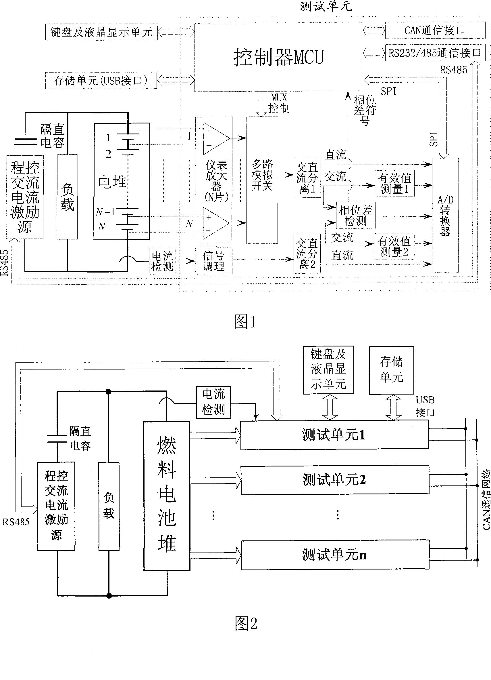
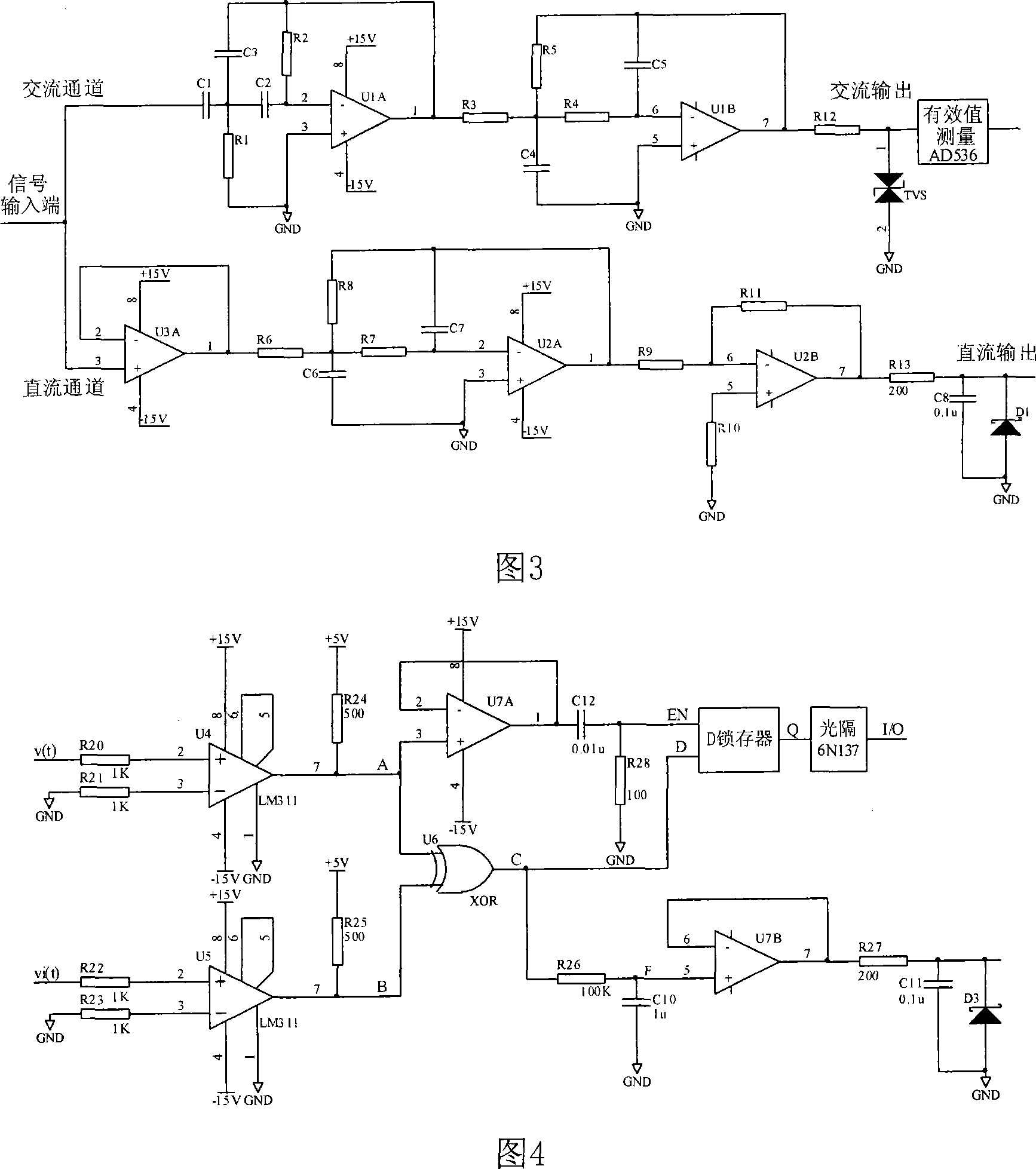
[0022] The invention includes a test unit, a programmable AC current excitation source and a DC blocking capacitor, a current detection module, a keyboard and a liquid crystal display unit, and a storage unit. The test unit consists of a controller MCU, instrumentation amplifier, multiple analog switches, signal conditioning circuits, and AC DC separation circuit, phase difference detection circuit, effective value measurement circuit, A/D converter, RS232/485 communication interface and CAN (control area network) communication interface (Figure 1), in which the program-controlled AC current excitation source is connected in series with a DC blocking capacitor Then it is connected in parallel with the fuel cell stack, so that a sinusoidal AC signal is superimposed on each single fuel cell. The voltage at both ends of each single cell is amplified 10 times by the instrumentation amplifier AD621 and then connected to the input of the multi-channel analog switch. The multi-channel analog switch is controlled by the controller MCU to output one of the voltages. This voltage enters the AC and DC separation of the voltage acquisition channel Circuit 1. The stack current is collected in real time by a precision closed-loop Hall current sensor and a precision sampling resistor. The voltage across the sampling resistor is amplified by 4 times by the instrumentation amplifier AD620 and then enters the AC/DC separation circuit 2 of the current collection channel. The AC output terminals of the two AC and DC separation circuits are respectively connected to the input terminals of the two RMS measurement chip AD536 and the phase difference detection circuit. The DC output terminal and the output terminal of the RMS measurement chip AD536 are directly simulated with the A/D converter TLC3548 Input channel connection. The A/D converter TLC3548 sends the analog-to-digital conversion result to the controller MCU in SPI mode. The controller MCU obtains the phase difference α of the AC voltage and current according to the phase difference sign and the analog-to-digital conversion result, and calculates the electric current according to the analog-to-digital conversion result. Stack AC current I AC , DC current I DC , The AC voltage of the monolithic battery V AC DC voltage V DC , And then calculate the internal resistance Z of the monolithic battery combined with the phase difference α:
[0023] Z = V AC I AC ( cos α + j sin α )
[0024] The controller MCU compares the internal resistance Z of the measured monolithic battery with the voltage V DC Send to the liquid crystal display unit for real-time display, and display an alarm for batteries whose internal resistance is greater than the warning value or the voltage is less than the warning value.
[0025]The multiple test units of the present invention can perform single-chip internal resistance and voltage tests on any number of fuel cell stacks through the CAN communication network connection. The multiple single-chip cells in the fuel cell stack are connected to the input of one test unit, and all single-chip cells are connected to the input of one test unit. The chip cell is connected to the input terminals of n test units, the program-controlled AC current excitation source and the DC blocking capacitor are connected in series with the output terminal of the fuel cell stack, and the current detection module is connected to the test unit 1 (Figure 2). Test unit 1 tests the internal resistance and voltage of multiple monolithic batteries, and also controls the program-controlled AC current excitation source in real time through the RS485 communication interface, collects the stack current, and sends the current value to other test units through the CAN communication network. Test unit 2 ~The internal resistance and voltage values ​​of multiple single-cell batteries tested by test unit n are sent to test unit 1 through the CAN communication network, and test unit 1 transmits all the internal resistance and voltage values ​​of all single-cell batteries to the LCD unit for display, and displays all The internal resistance and voltage value of the single-chip battery are sent to the storage unit through the USB interface for storage, and the test system communicates with the PC or other devices through the RS232/485 communication interface of the test unit 1.
[0026] The AC/DC separation circuit 1 of the voltage acquisition channel of the present invention is the same as the AC/DC separation circuit 2 of the current acquisition channel. The AC/DC separation circuit is composed of a second-order high-pass active filter circuit, a voltage follower, and a second-order low-pass active filter circuit. AC channel and DC channel (Figure 3).
[0027] 1. The AC channel of the AC/DC separation circuit is composed of a second-order high-pass active filter circuit and a second-order low-pass active filter circuit to output a 100Hz-20kHz signal, its output terminal is a current-limiting resistor R12, and a transient voltage suppressor TVS A limiter output protection circuit is formed to clamp the output at -V T To +V T In between, protect the safety of the effective value measuring chip AD536 and subsequent devices. The transfer function of the second-order high-pass active filter circuit is:
[0028] A F ( s ) = - C 1 C 3 S 2 S 2 + 1 R 2 ( C 1 C 2 C 3 + 1 C 2 + 1 C 3 ) S + 1 R 1 R 2 C 2 C 3
[0029] Where the passband gain: A F ( ∞ ) = - C 1 C 3
[0030] Lower limit frequency: f n = 1 2 π R 1 R 2 C 2 C 3
[0031] Damping coefficient: ϵ = 1 2 R 1 R 2 ( C 1 C 2 C 3 + C 2 C 3 + C 3 C 2 )
[0032] According to A F (∞)=-1, f n = 100Hz, ε = 0.707 and the actual resistance and capacitance parameter limits, take C1 = C2 = C3 = 0.1μF, R1 = 7.5kΩ, R2 = 36kΩ, the actual second-order high-pass active filter circuit A F (∞)=-1, f n =97Hz, ε=0.685, which can meet the system's 100Hz high-pass filtering requirements. The second-order low-pass active filter circuit and the second-order high-pass active filter circuit have duality. Replace the resistance in the second-order high-pass active filter circuit with a capacitor, and the capacitor with a resistor, then the second-order low-pass active filter can be obtained. The circuit also determines the actual parameters of each resistor and capacitor according to the passband gain, upper limit frequency, and damping coefficient.
[0033] 2. The DC channel of the AC/DC separation circuit is composed of a voltage follower U3, a second-order low-pass active filter circuit and an amplifying circuit. The limiting output protection circuit formed by the current limiting resistor R13 at the output and the voltage regulator tube D1 makes it Output is clamped -0.7V to +V D In between, protect the safety of the A/D converter TLC3548 and subsequent devices, so as not to damage the circuit and chip. The second-order low-pass active filter circuit and the second-order high-pass active filter circuit have duality. The resistance and capacitance parameters of the second-order low-pass active filter circuit are determined by referring to the above-mentioned AC channel second-order high-pass active filter circuit parameters.
[0034] The phase difference test circuit of the present invention adopts a voltage comparator LM311 to analyze the sinusoidal AC voltage signal V(t) and the current signal V i (t) Reshape, V(t) and V i (t) After being shaped by the voltage comparator LM311, the square waves A and B are output. A and B output C pulse through the exclusive OR circuit (Figure 4). The Fourier series expression is:
[0035] U C ( t ) = 5 q + Σ n = 1 ∞ ( a n cos nωt + b n sin nωt )
[0036] Where q is the duty cycle of C pulse, ω=400π~12000π, a n And b n Is a constant. C pulse elapsed time constant RC≥10T (T=2π/ω is the period of C pulse, T max ≤0.005S, here select R26=100kΩ, C10=1μF to meet the 1.59Hz low-pass filter requirements, fully meet the system requirements) low-pass active filter circuit output stable voltage U F , Which is U C Average value of (t):
[0037] U F = 5 q = 5 | α | π , ( 0 ≤ U ≤ 5 V )
[0038] U F The limiting output protection circuit formed by the current limiting resistor R27 and the voltage regulator tube D3, the output of which is clamped at -0.7V to +V D Between, and then enter TLC3548 for analog-to-digital conversion, the resolution is:
[0039] 5/2 14 =0.305mV
[0040] according to | α | = π U F 5 It can be seen that the resolution of the phase difference |α| is 6.1π×10 -5 radian. The RC differential circuit and the D latch are used to determine the sign of the phase difference between A and B. The output Q of the D latch is connected to the input I/O port of the controller MCU through the optical isolation 6N137. Q=1 means that the voltage is ahead of the current, and the sign of the phase difference is positive; Q=0 means the sign of the phase difference is negative, which actually indicates that the internal resistance of the fuel cell is inductive, capacitive or purely resistive.
[0041] The accuracy of this phase difference test method is as high as 6.1π×10 -5 Radian, and the accuracy is not affected by the size of the input signal frequency, which is very suitable for the situation where the signal frequency changes in a large range in this system. The test range is -π~π, and there is no test dead angle.
[0042] The content not described in detail in this specification belongs to the prior art known to those skilled in the art.

PUM

no PUM

Description & Claims & Application Information

We can also present the details of the Description, Claims and Application information to help users get a comprehensive understanding of the technical details of the patent, such as background art, summary of invention, brief description of drawings, description of embodiments, and other original content. On the other hand, users can also determine the specific scope of protection of the technology through the list of claims; as well as understand the changes in the life cycle of the technology with the presentation of the patent timeline. Login to view more.

Similar technology patents

Oil charging self-adaptive control method and system for wet clutch

ActiveCN105782286AGuaranteed adjustment accuracyPracticalClutchesClutchSelf adaptive
Owner:ANHUI JIANGHUAI AUTOMOBILE GRP CORP LTD

Feeder fault handling method

Owner:HUNAN ELECTRIC POWER CORP RES INST +2

Classification and recommendation of technical efficacy words

  • Simple circuit
  • Practical

Booth multiplier

ActiveCN102722352ASimple circuitOccupies a small number of transistorsDigital data processing detailsWallace treePartial product
Owner:SOUTH CHINA UNIV OF TECH

Optimization method for spray gun track of spraying robot on irregular polyhedron

ActiveCN102500498APracticalImprove work efficiency and product qualitySpraying apparatusSpecial data processing applicationsComputer Aided DesignParticle swarm algorithm
Owner:JIANGSU NEWBLUE INTELLIGENT EQUIP CO LTD
Why Eureka
Try Eureka