
Process and system for gas freeing on board of a vessel or other installation

A gas and air technology, applied in the field of degassing and systems, can solve complex and time-consuming problems, achieve low operating costs and save the environment

Active Publication Date: 2008-07-23
WARTSILA MOSS AS
View PDF1 Cites 3 Cited by
  • Summary
  • Abstract
  • Description
  • Claims
  • Application Information

AI Technical Summary

Problems solved by technology

This is an acceptable method, but it is complex and thus time consuming, which has adverse economical implications

Method used


Image

  • Process and system for gas freeing on board of a vessel or other installation
  • Process and system for gas freeing on board of a vessel or other installation
  • Process and system for gas freeing on board of a vessel or other installation

Examples


Embodiment Construction

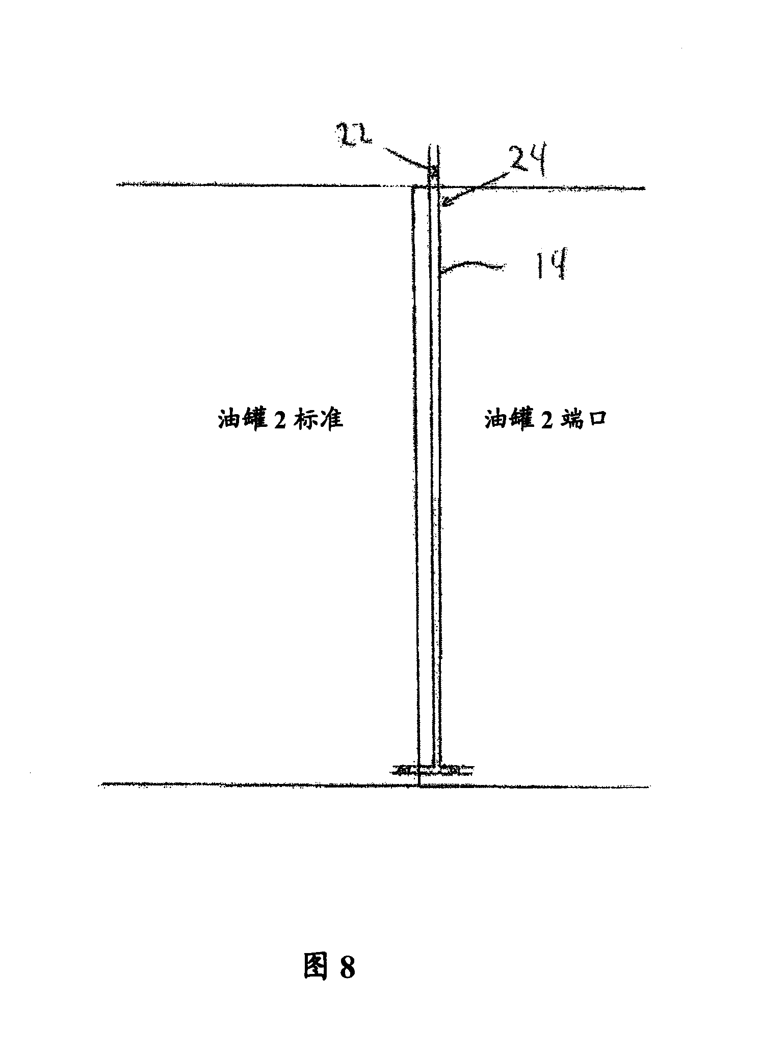
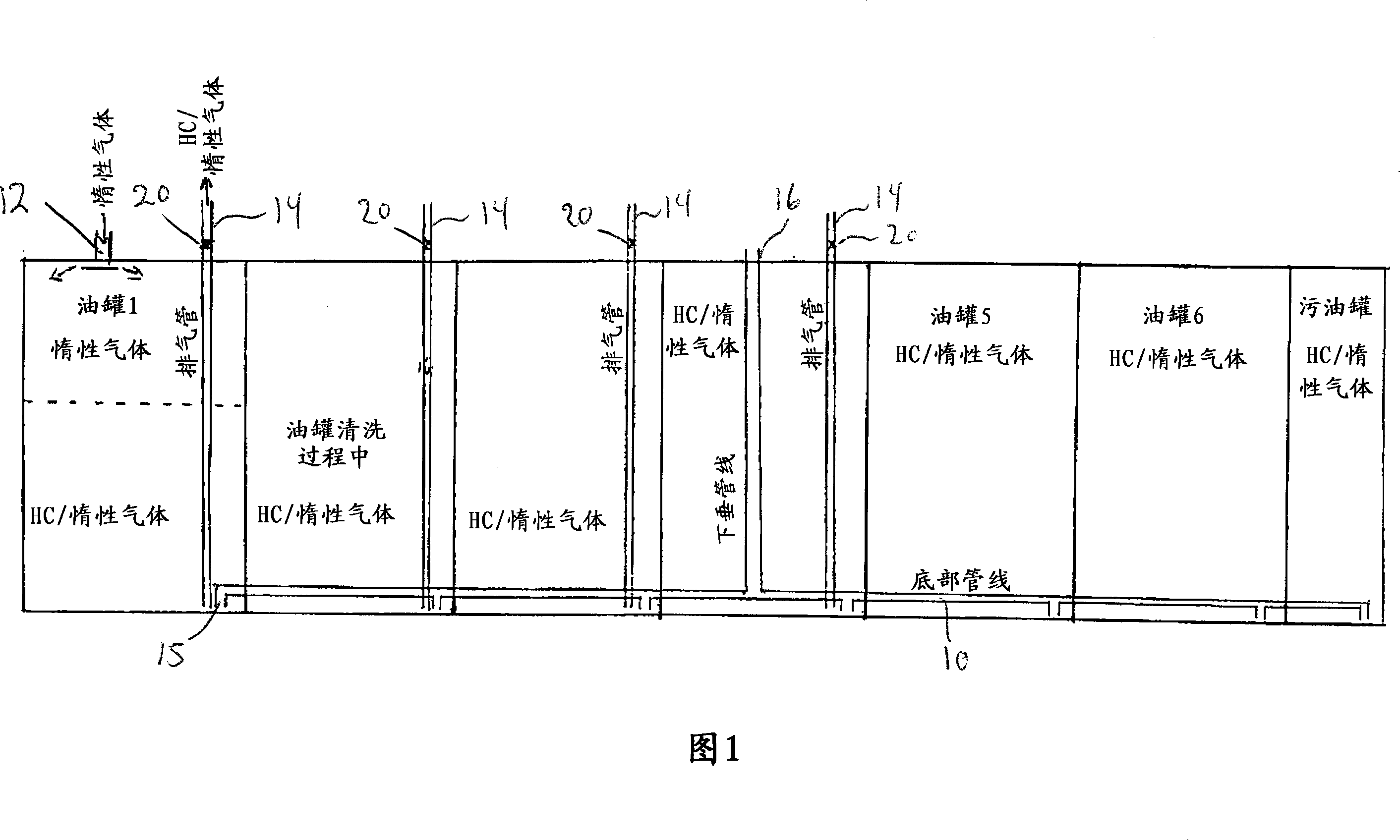
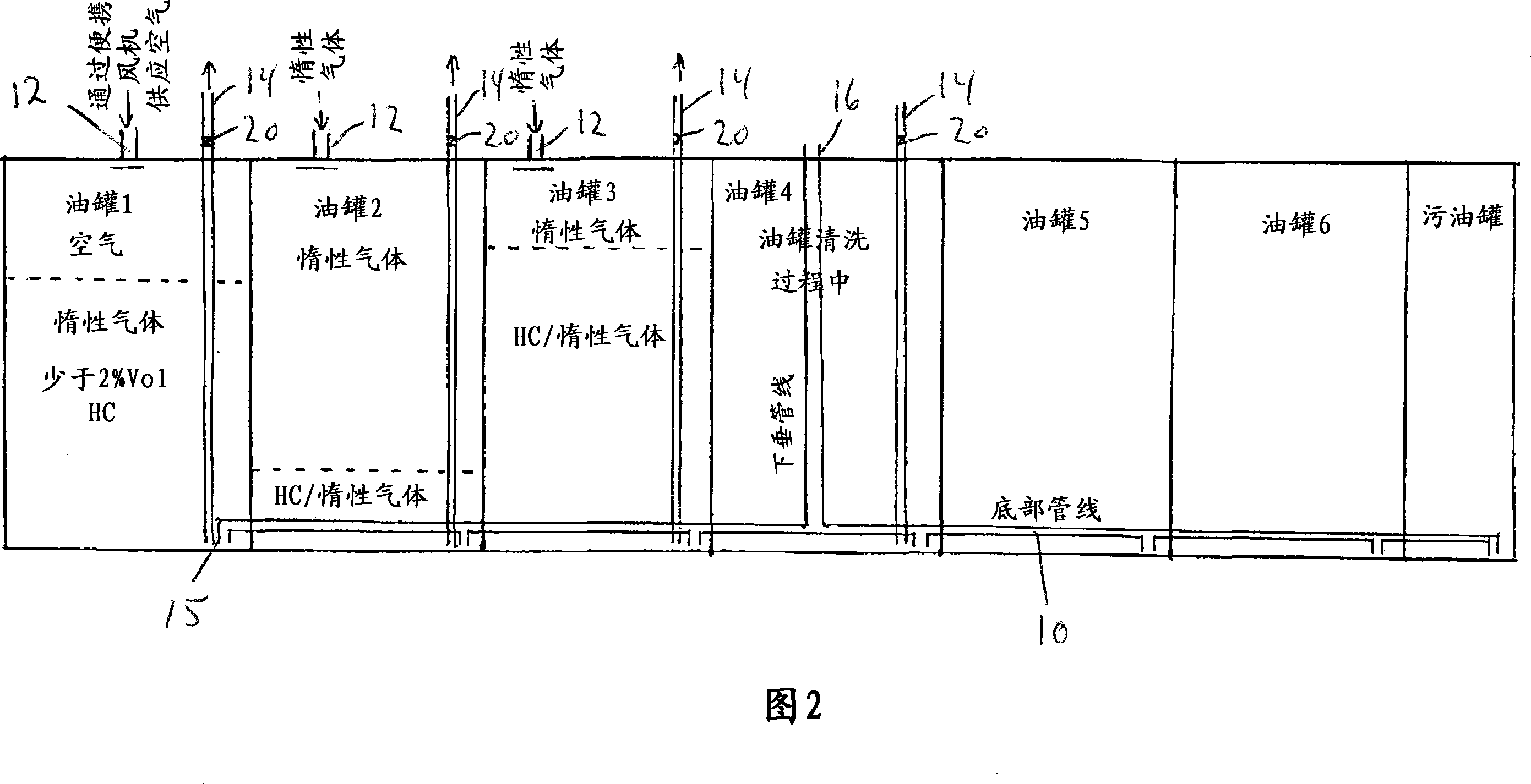
[0025] When the tank leaves the unloading port and is about to enter the workshop, the tank must be cleaned. After that, an inert gas must be supplied in order to reduce the concentration of HC gas to below 2% by volume (Vol.). Then, air was blown in so as to reduce the concentration of HC gas to 1% by volume of 2%. This is called 1% LEL - Lower Explosion Limit. At this time, it is possible to work in the oil tank. Large tankers have tanks eg 20-25m deep and it is time consuming to get the bottom of the tank to 1% LEL if the gas is blown in from the top and the heaviest gas is at the bottom. By utilizing the difference in specific gravity, the HC / inert gas is pressed out from the bottom. The LEL% will also be the highest concentration at the bottom of the tank. The limits of 2% HC and 1% LEL by volume are international requirements.

[0026] During the cleaning of the oil tank, for example, two pumps can be used. One of them supplies pressure to the jet scrubber and suct...


PUM


Abstract

The invention discloses a degassing system on the ship or the other device, comprising a plurality of adjacent oil tanks connected by the bottom pipeline system. After emptying the oil, the oil tank is filled with gas such as carburetted hydrogen gas. The oil tank comprises at least one air intake for receiving and guiding the gas with specific gravity less than the existing gas in the oil tank such as inert gas and / or air; and an exhaust port for outputting the mixture of the existing gas and the supplied gas. A plurality of oil tanks mounted before the pendulous pipeline in the oil tank array or adjacent to the oil tank array ventilate the mixture of the existing gas and the supplied gas from the bottom of the oil tank by a vertical vent pipe, wherein the vertical vent pipe extends from the bottom of the adjacent oil tank and extends outside the oil tank. A plurality of oil tanks mounted behind the pendulous pipeline in the oil tank array ventilate the mixture of the existing gas and the supplied gas from the bottom of the oil tank by a bottom pipeline system and comes out from the pendulous pipeline.

Description

technical field [0001] The present invention relates to a system and method for degassing on board a ship or other equipment, wherein the system includes a plurality of adjacent tanks containing gas in gaseous state, such as hydrocarbon gas, passing through the tanks At least one gas inlet of each oil tank in the row sequentially feeds gas having a specific gravity smaller than that of the gas in the oil tank. Background technique [0002] Volatile gases are often transported in tanks on ships or other equipment. When this gas is unloaded, the gas in the tank boils off and must be removed before any work can be done on the tank and before servicing the tank. [0003] Supplying inert gas to tanks on board ships is a standard procedure during unloading and venting. The advantage of inert gases is their low oxygen content. Before the mandatory use of inert gas equipment, air entered the tank during unloading and sat above the existing crude oil. The gas mixture thus produce...

Claims


Application Information

Patent Timeline
IPC IPC(8): B65D90/44B63B25/08
CPCY02T70/72Y02T70/00B63B57/04B63J2/08B65D90/22
Inventor 马格纳尔·布拉利德
Owner WARTSILA MOSS AS
Learn More