
Microbiological fuel cell of baffle plate air cathode

An air cathode and fuel cell technology, applied to biochemical fuel cells, fuel cell parts, battery electrodes, etc., can solve the problems of single wastewater type, low energy density, single structure, etc., to save reactor space and improve treatment Efficiency, the effect of improving power density

Active Publication Date: 2008-07-23
HARBIN INST OF TECH
View PDF0 Cites 31 Cited by
  • Summary
  • Abstract
  • Description
  • Claims
  • Application Information

AI Technical Summary

Problems solved by technology

[0004] The purpose of the present invention is to solve the problem that the anode of the existing microbial fuel cell mostly uses carbon paper or carbon cloth, has a single structure, has a large internal resistance, and has a very low energy density. Disadvantages of providing a baffled air cathode microbial fuel cell

Method used


Image

  • Microbiological fuel cell of baffle plate air cathode
  • Microbiological fuel cell of baffle plate air cathode
  • Microbiological fuel cell of baffle plate air cathode

Examples


specific Embodiment approach 1

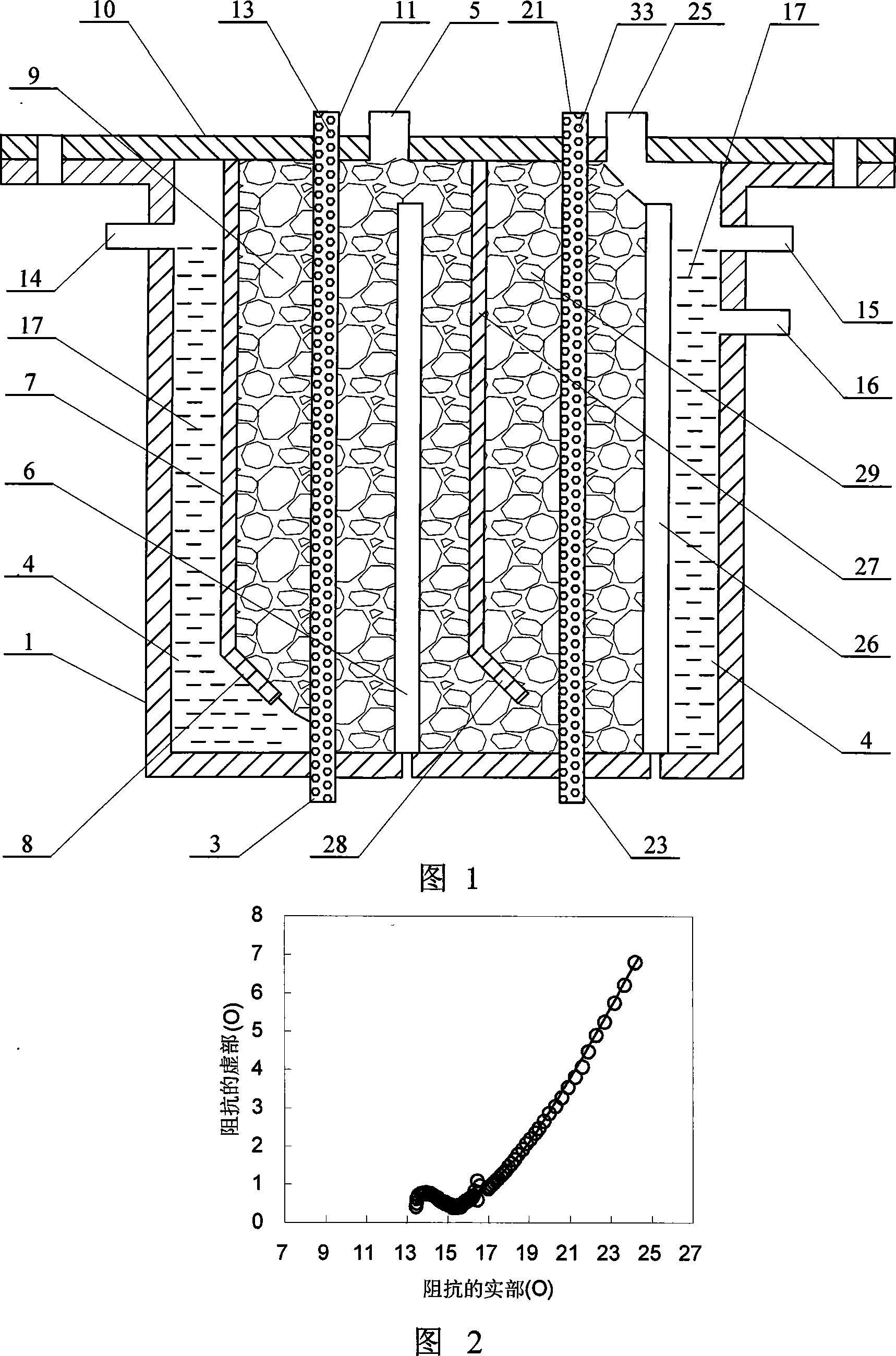
[0008] Specific embodiment one: (referring to Fig. 1) present embodiment is made up of box body 1, the first three-dimensional solid anode, the first air cathode 3, the first plastic baffle plate 7, sealing cover 10 and solution 17, on the sealing cover 10 A first sampling port 5 is provided, a water inlet 14 is provided on one side of the upper part of the side wall of the cabinet 1, a water outlet 15 is provided on the other side of the upper part of the side wall of the cabinet 1, and a sealing cover is provided on the top of the cabinet 1 10. The box body 1 is sealed and connected with the sealing cover 10. The anode chamber 4 is between the sealing cover 10 and the cavity of the box body 1. The first air cathode 3 is arranged between the sealing cover 10 and the box body 1. The first air cathode The upper end of 3 is fixedly connected with the sealing cover 10 and communicated with the atmosphere. The lower end of the first air cathode 3 is fixedly connected with the botto...

specific Embodiment approach 2

[0009] Specific embodiment two: (referring to Fig. 1) the difference between this embodiment and specific embodiment one is that it has increased the second three-dimensional anode, the second air cathode 23 and the second plastic baffle plate 27, the second three-dimensional anode , the second air cathode 23 and the second plastic baffle 27 are all arranged in parallel with the first three-dimensional solid anode, the first air cathode 3 and the first plastic baffle 7, and the second air cathode 23 is arranged between the sealing cover 10 and the box Between the body 1, the upper end of the second air cathode 23 is fixedly connected with the sealing cover 10 and communicated with the atmosphere, the lower end of the second air cathode 23 is fixedly connected with the bottom of the box body 1 and communicated with the atmosphere, the second air cathode 23 It is composed of a second cylindrical plastic substrate 21 covered with carbon cloth on the surface. The second cylindrical...

specific Embodiment approach 3

[0011] Embodiment 3: (see FIG. 1 ) The difference between this embodiment and Embodiment 1 is that a return port 16 is provided on the box body 1 below the water outlet 15 . The return port 16 is used to connect with the return device, and return part of the outlet water to the tank 1 through the water inlet 14 for reuse. Others are the same as in the first embodiment.


PUM

PropertyMeasurementUnit
Diameteraaaaaaaaaa
Chamferaaaaaaaaaa

Abstract

A deflector air cathode microbe fuel cell relates to a microbe fuel cell. The purpose of the invention is made to resolve the problems that the prior microbe fuel cell anode which adopts carbon paper or carbon cloth results in little biology adhesion weight of electrogenesis microbe, considerable internal resistance, greatly low energy density and much energy consumption. The air cathode of the invention is made of a cylindrical plastic basal body which is covered with the carbon cloth on surface and is arranged with a through-hole, a plastic deflector is arranged on the one side of the air cathode, the upper end of the plastic deflector is fixedly connected with floor of an airtight cover, and the lower portion of the plastic deflector is arranged with a baffling angle plate. The invention has the advantages of effectively improving biology adhesion weight and output energy, and increasing electron collection area through adopting three-dimensional composite anode instead of the carbon paper and carbon cloth, extending contact area, reducing electrode spacing, effectively reducing internal resistance of a reactor and greatly improving power density through placing the cathode in an anode chamber.

Description

technical field [0001] The invention relates to a microbial fuel cell. Background technique [0002] With the increasing shortage of energy, it has become the consensus of the whole world to develop new clean energy and adjust the energy structure. Microbial fuel cell (MFC) is a new type of device that utilizes biomass and microorganisms to produce electric energy. As an important part of batteries, cathode and anode have received a lot of attention. The development and improvement from shape to material has become one of the main means to increase output energy. Microbial fuel cells are generally composed of two chambers, an anode chamber and a cathode chamber, in the form of an "H", separated by a cation exchange membrane such as Nafion or Ultrex, or separated by a common salt bridge. This type of reactor uses the dissolved oxygen in the catholyte as the electron acceptor, the contact area is small, and the amount of oxygen is greatly affected by the dissolution and dif...

Claims


Application Information

Patent Timeline
IPC IPC(8): H01M8/16H01M8/02H01M4/86
CPCH01M4/8605H01M4/96H01M8/16Y02E60/50
Inventor 冯玉杰李贺王鑫
Owner HARBIN INST OF TECH
Learn More