Electron accelerator

An electron accelerator and electron gun technology, applied in the direction of DC voltage accelerators, electrical components, accelerators, etc., can solve problems such as slow response time, low reliability, and limited adjustment range, and achieve stable output, fast response speed, and wide adjustment range Effect

Active Publication Date: 2010-07-28
CGN DASHENG ELECTRON ACCELERATOR TECH
View PDF6 Cites 0 Cited by
  • Summary
  • Abstract
  • Description
  • Claims
  • Application Information

AI Technical Summary

Problems solved by technology

[0004] Such a power supply method and device has complex structure, troublesome control, low stability and reliability, and limited adjustment range.
There are mainly the following problems: 1) When adjusting the filament voltage, it is necessary to change the angle of the two potentiometers for coarse adjustment and fine adjustment by adjusting the servo motor, and the response time is relatively slow, which cannot meet the requirements of fast tracking; 2) The filament current That is to say, it is difficult to maintain a strict single correspondence between the adjustment of the accelerator beam current and the adjustment of the servo motor, which brings a lot of inconvenience to the automatic tracking of the device under the beam; 3) When the accelerator works at a lower end voltage, the high The frequency voltage is also low, and the voltage input to the electron gun power supply circuit through coupling is also low. When the terminal voltage is low to a certain value, the voltage stabilizing component will not work. At this time, the heating current of the filament will change with the change of the accelerator terminal voltage.
And because the voltage input to the filament transformer is too low, the beam current cannot reach the rated value
Therefore, if the accelerator powered by this coupling method does not take other supplementary measures, the working range of its terminal voltage will be limited; 4) The brush of the potentiometer will be worn out, and the voltage stabilizing component is also easy to be damaged, so the failure rate is high and reliable. Low resistance, short service life

Method used


Image

  • Electron accelerator
  • Electron accelerator

Examples


Embodiment Construction

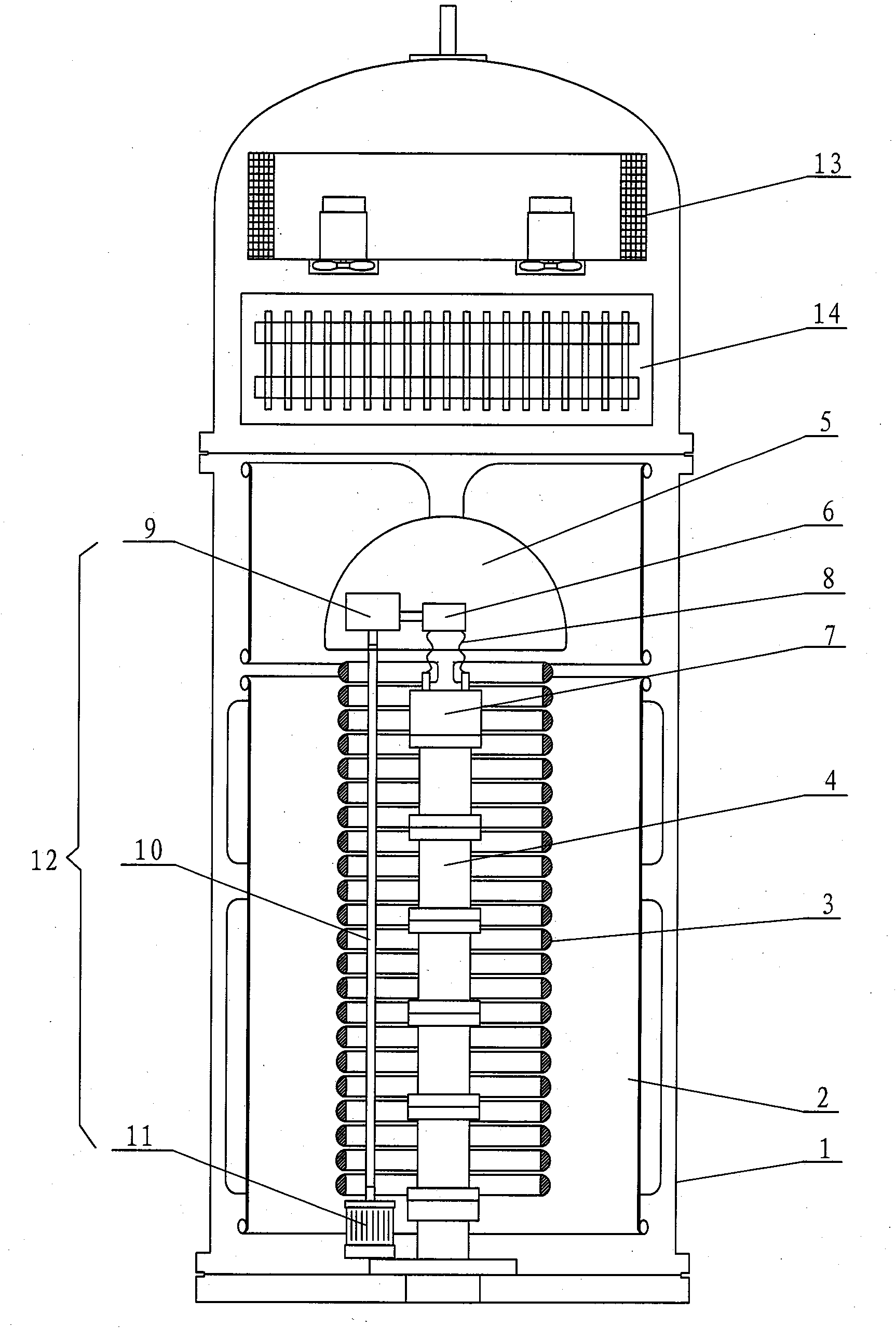
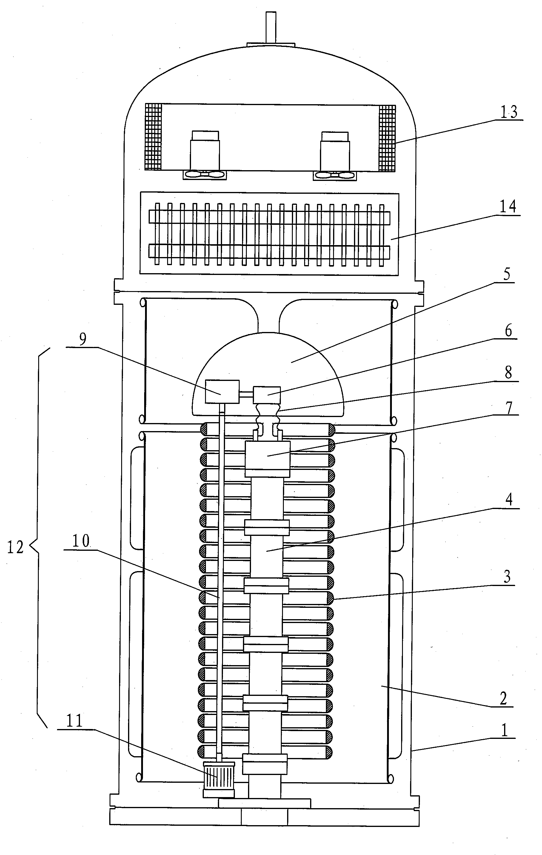
[0013] Such as figure 1 The electron accelerator shown includes a steel cylinder 1, a cold trap 13 arranged above the steel cylinder 1, a high-frequency transformer 14 arranged below the cold trap 13, and a plurality of semicircular corona rings 3 arranged inside the steel cylinder 1 , two high-frequency electrodes 2 arranged outside the corona ring 3, a high-voltage electrode 5 arranged above the corona ring 3, an electron gun 7 with a filament 8 for generating and exciting electrons, and a vacuum arranged below the electron gun 7 The accelerating tube 4, the filament transformer 6 connected to the filament 8 for adjusting the voltage of the filament 8, the filament power supply system 12 connected to the filament transformer 6 for supplying power to the electron gun 7, and a plurality of semicircular corona rings 3 Arranged symmetrically along the axis of the steel cylinder 1 with openings facing each other, the electron gun filament power supply system 12 includes a motor ...


PUM


Abstract

An electron accelerator comprises a steel cylinder, a high-frequency transformer, two lines of semi-circular corona rings which are arranged inside the steel cylinder, a high pressure electrode which is arranged on the corona rings, two pieces of high-frequency electrodes which are arranged outside the corona rings and the high pressure electrode, an electron gun which is used to produce and excite electrons with a filament, a vacuum accelerating tube which is arranged under the electron gun, a filament transformer which is electrically connected on the filament and is used to regulate filament voltage and an electron gun filament power supply system which is electrically connected on the filament transformer and is used to supply power to the electron gun, the electron gun filament powersupply system comprises an electromotor which is arranged on the bottom of the steel cylinder and located under the corona rings, a centre rod whose one end portion is connected with an output end ofthe electromotor and an electric generator which is arranged inside the high pressure electrode and is electrically connected with the filament transformer, wherein the other end portion of the centre rod is connected with an input end of the electric generator and the centre rod is arranged inside an opening part of the semi-circular corona rings along the axial direction of the steel cylinder. The accelerator has the characteristics of simple structure, low cost, rapid response speed, stable supply voltage and convenient automatic control.

Description

Technical field [0001] The invention involves an electronic accelerator. Background technique [0002] Among the existing technologies, the electronic accelerator consists of the following components: a steel cylinder, a cold trap set at the top of the steel tube, a high -frequency transformer set on the top of the steel tube, the high -voltage electrode, core column set at the below high -frequency transformer, along the steel along the steelThe distinctive arrangement of the tube center line is arranged in the two -row halo ring set on the core column, the rectifier silicon piles set in the core column, the high -frequency transformers are connected, and the two high -frequency electrodes of the two rows of halo rings are set.The electronic gun used to stimulate the electronics, the vacuum acceleration tube located below the electronic gun, the electronic gun power supply device for electronic guns, the filament transformer used to regulate the electronic gun filament voltageFr...

Claims


Application Information

Patent Timeline
Patent Type & Authority Patents(China)
IPC IPC(8): H05H5/00
Inventor 斯厚智高文照俞章华
Owner CGN DASHENG ELECTRON ACCELERATOR TECH
Why Eureka
Try Eureka