
Method for forming phototonus combination, direction distribution membrane and optical compensation membrane

A photosensitive composition and photosensitivity technology, applied in nonlinear optics, optics, optomechanical equipment, etc., can solve problems such as dust pollution, unsuitable wide viewing angle, scratches, etc.

Active Publication Date: 2008-07-30
IND TECH RES INST
View PDF0 Cites 10 Cited by
  • Summary
  • Abstract
  • Description
  • Claims
  • Application Information

AI Technical Summary

Problems solved by technology

Although this method is simple and the alignment is stable, there are many problems as follows: (1) Dust pollution, static residue, and scratches generated by brushing
(2) A single direction will result in a narrow viewing angle, which does not conform to the trend of wide viewing angles
[0012] The above three materials all require high exposure to form an alignment effect, which has a great impact on the yield. Therefore, how to provide a novel material that can overcome the above problems, has a highly photosensitivity composition, and can be used at low exposure Having an excellent alignment effect after illumination is an important goal of the present invention

Method used


Image

  • Method for forming phototonus combination, direction distribution membrane and optical compensation membrane
  • Method for forming phototonus combination, direction distribution membrane and optical compensation membrane
  • Method for forming phototonus combination, direction distribution membrane and optical compensation membrane

Examples


Embodiment 1-1

[0033] Copolymer of 4-(methacrylamido)phenylmethacrylate and perfluorinated propyl methacrylate1

[0034] Take 0.5g (2mmol) of 4-(methacrylamide) phenyl methacrylate, 0.375g (1.4mmol) of perfluorinated propyl methacrylate (2,2,3,3-tetrafluoropropylmethacrylate) and 0.00875g of AIBN was dissolved in 10mL of DMF and isolated from the air. After reacting at 80°C for 20 minutes, the reactant was slowly dropped into diethyl ether (200mL) under stirring at room temperature. After filtration, 0.374 g (42.7% yield) of copolymer 1 was obtained. IR(KBr), cm -1 : Broad peak (broad) 3430, 3350 (N-H), 1750 (-O-C-O-), 1670 (amide), 1510, 1260, 962, 945, 879, 661 (aryl), other signals such as 2940, 1410, 1390, 1320, 1200, 1170, 1130, 1100, 1002, 833, 525.

[0035] Copolymer of 4-(methacrylamido)phenyl methacrylate and perfluorinated propyl methacrylate 2

[0036] Take 0.91g (4mmol) of 4-(methacrylamido)phenyl methacrylate, 1g (5mmol) of perfluorinated propyl methacrylate and 0.0191g of A...

Embodiment 1-2

[0050] Preparation of Alignment Film

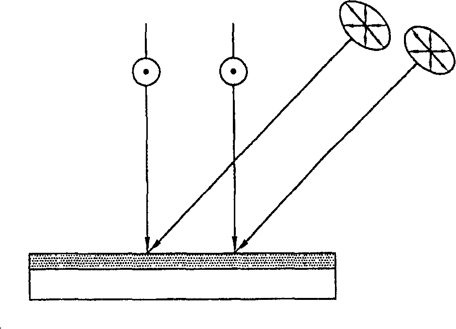
[0051] 80 parts by weight of copolymer 1-8, 10 parts by weight of dipentylthritol hexaacrylate (DPHA), and 5 parts by weight of photoinitiator were respectively dissolved in DMF to form a photosensitive composition solution. Then, the above solution was spin-coated onto the glass containing the ITO electrode at a speed of 3500 rpm, and baked at 180° C. for 1.5 hours to remove DMF. Then the substrate is taken out from the oven and returned to room temperature, and the photosensitive composition film on the substrate is irradiated with ultraviolet rays generated by a high-pressure mercury lamp, such as figure 1 shown. First, irradiate the film with polarized ultraviolet light at an angle of 45 degrees (exposure amount is about 50mJ / cm 2 ). Afterwards, a polarizing plate was added, and the film was irradiated vertically with unpolarized ultraviolet light (exposure amount was about 50mJ / cm 2 ), forming an alignment film. The above polari...


PUM


Abstract

The invention provides a light-sensitive composite which contains a light-sensitive polymer, a light-sensitive monomer and a photo-induced compound. The composite can be used as alignment film or optical compensation film in a liquid crystal display through UV curing. The repetitive units of the light-sensitive polymer are two kinds of olefinic bond, wherein one kind of olefinic bond can polymerize to form the main chain and the other kind of olefinic bond can undergo two-stage UV treatment to form the alignment film. Additionally, the light-sensitive monomer contains more than two olefinic bonds, so that the light susceptibility is improved and the UV exposure is reduced.

Description

technical field [0001] The present invention relates to a photosensitive composition, and more particularly, to a method for forming a photoalignment film or an optical compensation film from the photosensitive composition. Background technique [0002] As the display area of ​​the display becomes larger and the thickness becomes thinner and thinner, how to further align the liquid crystal molecules has always been an important issue in the development of the liquid crystal display. In this field of research, in addition to the research and development of liquid crystal molecules, the design of alignment films and optical compensation films is also a focus. In the prior art, the alignment film is usually formed by forming a polymer film on a substrate, and aligning it by directional rubbing. Although this method is simple and has stable alignment, there are many problems as follows: (1) Dust pollution, static electricity residue, and scratches generated by brushing. (2) A ...

Claims


Application Information

Patent Timeline
IPC IPC(8): G03F7/027G03F7/028G02F1/1337G02B5/30G02F1/1335
Inventor 林松香李政道李文钦
Owner IND TECH RES INST
Learn More