Differential jumping frequency G function construction method

A technology of differential frequency hopping and construction method, applied in electrical components, transmission systems, etc., can solve the problems that randomness, one-dimensional uniformity and two-dimensional continuity cannot be fully satisfied, performance is not superior enough, and system complexity is high. Good anti-interception performance, simple structure, good anti-interference effect

Inactive Publication Date: 2008-08-13
PLA UNIV OF SCI & TECH
View PDF0 Cites 16 Cited by
  • Summary
  • Abstract
  • Description
  • Claims
  • Application Information

AI Technical Summary

Problems solved by technology

[0005] The problem to be solved by the present invention is: the performance of the differential frequency hopping code sequence of the existing differential frequency hopping G function is not superior enough, and cannot fully satisfy the indicators such

Method used


Image

  • Differential jumping frequency G function construction method
  • Differential jumping frequency G function construction method
  • Differential jumping frequency G function construction method

Examples


Embodiment 1

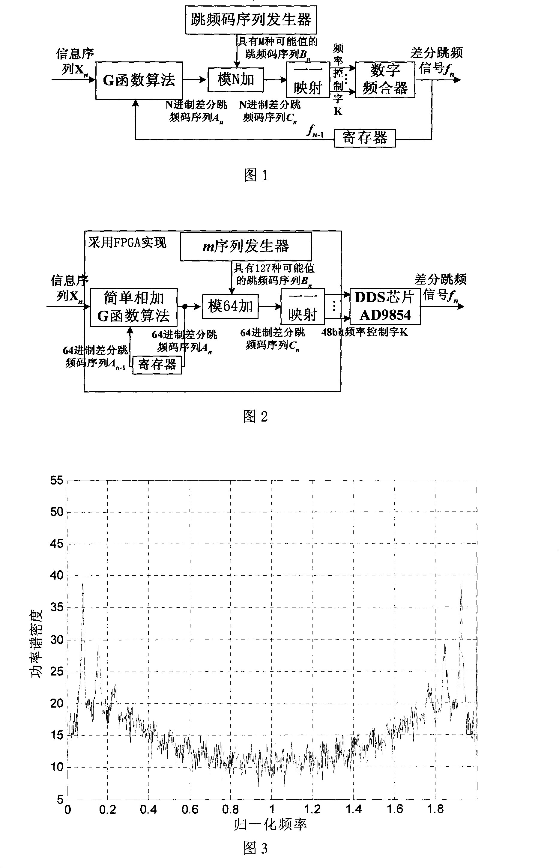
[0021] As shown in Fig. 2, the method of the present invention is implemented by an FPGA chip and a DDS chip. The DDS chip is AD9854, the reference clock is 100MHz, and the frequency control word is 48 bits to realize the digital frequency combiner function. Information sequence X n Enter the FPGA chip, the FPGA chip outputs a set of frequency control word K into the DDS chip AD9854, and the DDS chip outputs a differential frequency hopping signal f according to the input frequency control word K n ; G function algorithm is a simple addition of G function, "Performance Analysis of Shortwave CHESS Frequency Hopping System" (Liu Zhongying, Journal of PLA University of Science and Technology (Natural Science Edition), October 2000) has an introduction to this function, due to frequency hopping The one-to-one mapping relationship between frequency and frequency hopping code sequence, the G function algorithm in this embodiment is A n =G(X n , A n-1 ). Simple addition G function algori...

Embodiment 2

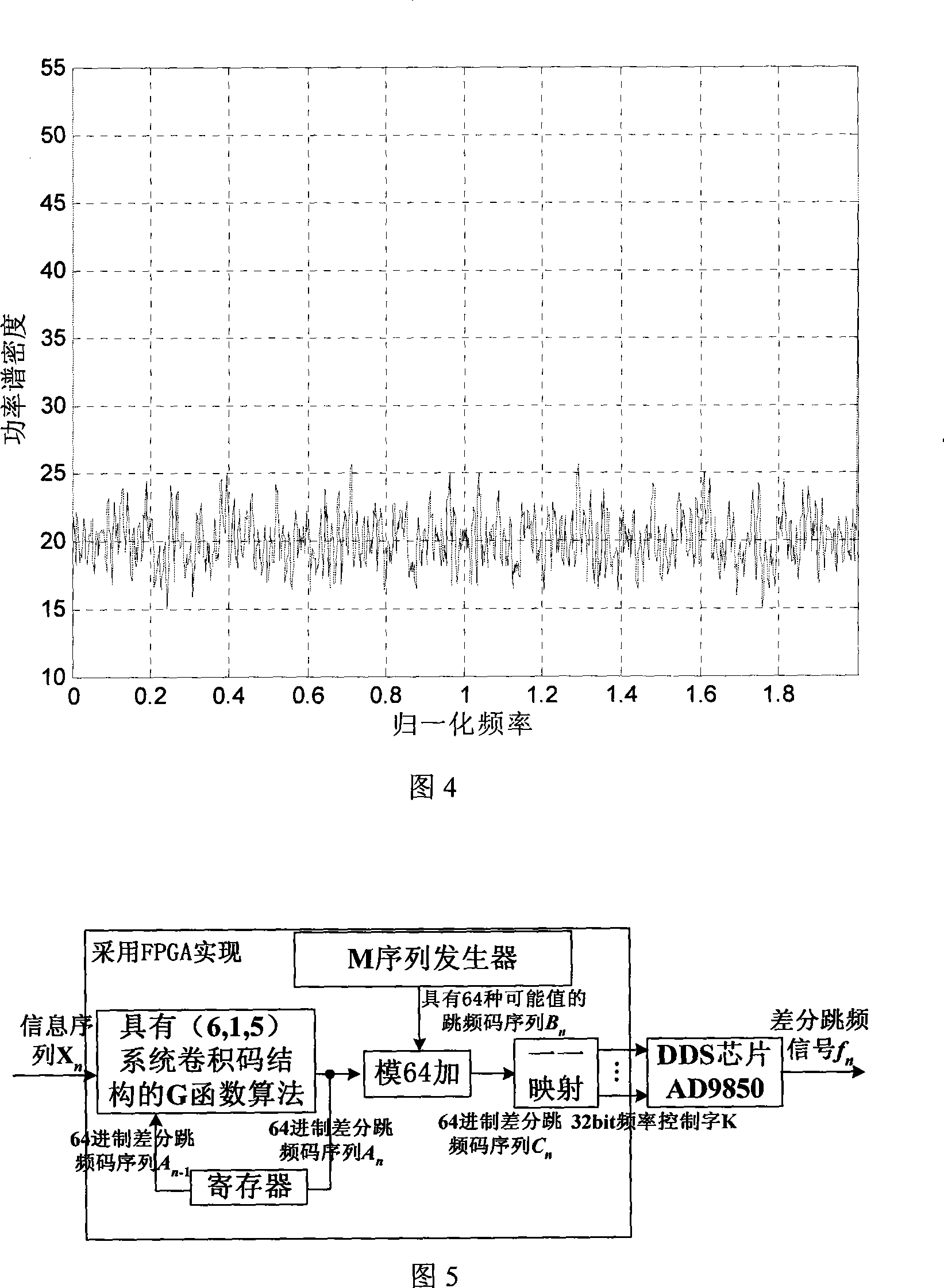
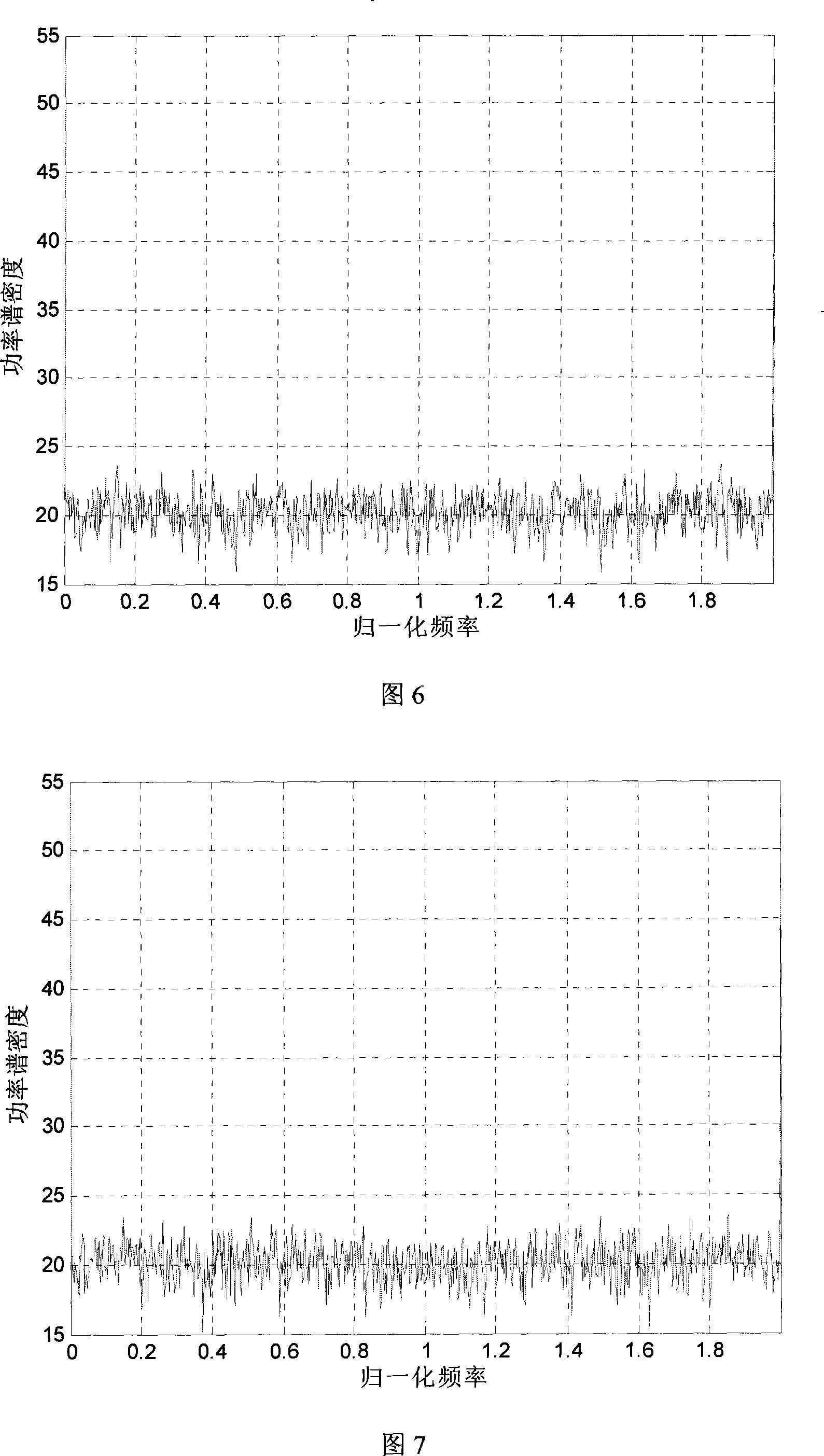
[0028] See Figure 5 for another practical example. Including FPGA chip and DDS chip, the DDS chip is AD9850, the reference clock is 10MHz, the frequency control word is 32 bits, and the digital frequency combiner function is realized. Information sequence X n Enter the FPGA chip, the FPGA chip outputs a set of frequency control word K into the digital frequency combiner, and the digital frequency combiner outputs a differential frequency hopping signal f according to the input frequency control word K n . The G function algorithm uses the G function with a (6, 1, 5) system convolutional code structure ("Analysis of Equivalent Convolutional Codes for Differential Frequency Hopping", Yang Baofeng, Journal of Jilin University (Information Science Edition), October 2006) , G function algorithm with (6, 1, 5) system convolutional code structure, M sequence generator, register, modulo N addition, 32bit frequency control word K generation, differential frequency hopping code sequence C n...


PUM


Abstract

A constructing method of difference frequency hopping G function is provided. Data X<n> transmitted presently and frequency of previous jump f<n-1> obtain frequency hopping code sequence A<n> corresponding to frequency of present difference frequency hopping. Number of frequency of present difference frequency hopping is N. the frequency hopping code sequence generator generates pseudorandom frequency hopping code sequence B<n>. Processing module N pulse for A<n> and B<n>, which obtains new difference frequency hopping code C<n>, controlling the digital frequency synthesizer to output final difference frequency hopping signal f<n> according to corresponding frequency control character K output by C<n>. the invention fully adopts present difference frequency hopping G function arithmetic and frequency hopping code sequence technology without altering structure of G function arithmetic; compared with the difference frequency hopping technology, only the frequency hopping code sequence generator and the module N pulse module are added with simple structure and easy implementation; finally output difference frequency hopping signal satisfies requirements of randomicity, one-dimension evenness and two-dimension continuity completely, having greater anti-interruption and anti-capturing performances.

Description

Technical field [0001] The invention belongs to the technical field of frequency hopping spread spectrum communication, relates to the generation of differential frequency hopping code sequences, and is specifically a method for constructing a differential frequency hopping G function with a simple structure. Background technique [0002] Spread spectrum communication is a technology commonly used in wireless communication systems, mainly used to counter or suppress the harmful effects of interference and to keep other listeners confidential. Frequency-hopping spread-spectrum communication is an important form of spread-spectrum communication, which is especially widely used in military communications. Compared with fixed frequency communication, the working frequency of frequency hopping communication system is constantly hopping, so that it can effectively avoid multipath interference and aiming interference, and its anti-interception ability is als...

Claims


Application Information

Patent Timeline
IPC IPC(8): H04B1/713H04B1/69H04B1/7136
Inventor 杨保峰沈越泓高媛媛李建东
Owner PLA UNIV OF SCI & TECH
Why Eureka
Try Eureka