
Active control type electrolysing solution flowing method in blade process and electrolysing solution circulating system

An electrolyte and control technology, which is applied in the direction of processing working medium supply, etc., can solve problems such as blank vibration, uneven electrolyte flow, and flow direction cannot be changed.

Inactive Publication Date: 2008-08-27
NANJING UNIV OF AERONAUTICS & ASTRONAUTICS
View PDF1 Cites 28 Cited by
  • Summary
  • Abstract
  • Description
  • Claims
  • Application Information

AI Technical Summary

Problems solved by technology

[0013] The purpose of the present invention is to meet the needs of blade electrolytic machining technology, overcome the uneven flow of electrolyte in blade electrolytic machining, the impact of a large amount of liquid on the blank causes the flow field in the processing area to be disordered, the blank vibrates, and the flow through the blade basin and blade back cannot be actively controlled , the flow direction cannot be changed, and the adaptability and flexibility are weak. With the goal of improving the machining accuracy and surface quality of the blade, it is possible to provide a method that can accurately control the flow of the blade pot and the blade back, and the state of the flow field is stable and uniform. Actively controlled electrolyte flow method and electrolyte circulation system in more extensive blade machining

Method used


Image

  • Active control type electrolysing solution flowing method in blade process and electrolysing solution circulating system
  • Active control type electrolysing solution flowing method in blade process and electrolysing solution circulating system
  • Active control type electrolysing solution flowing method in blade process and electrolysing solution circulating system

Examples


Embodiment Construction

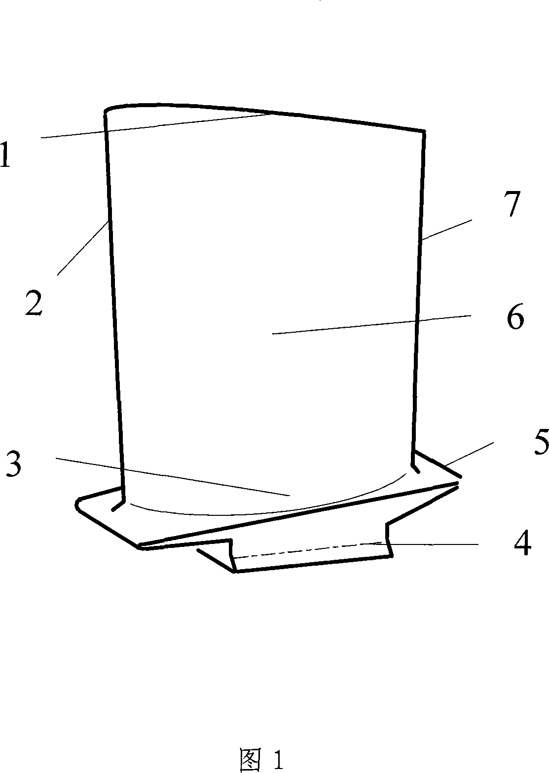
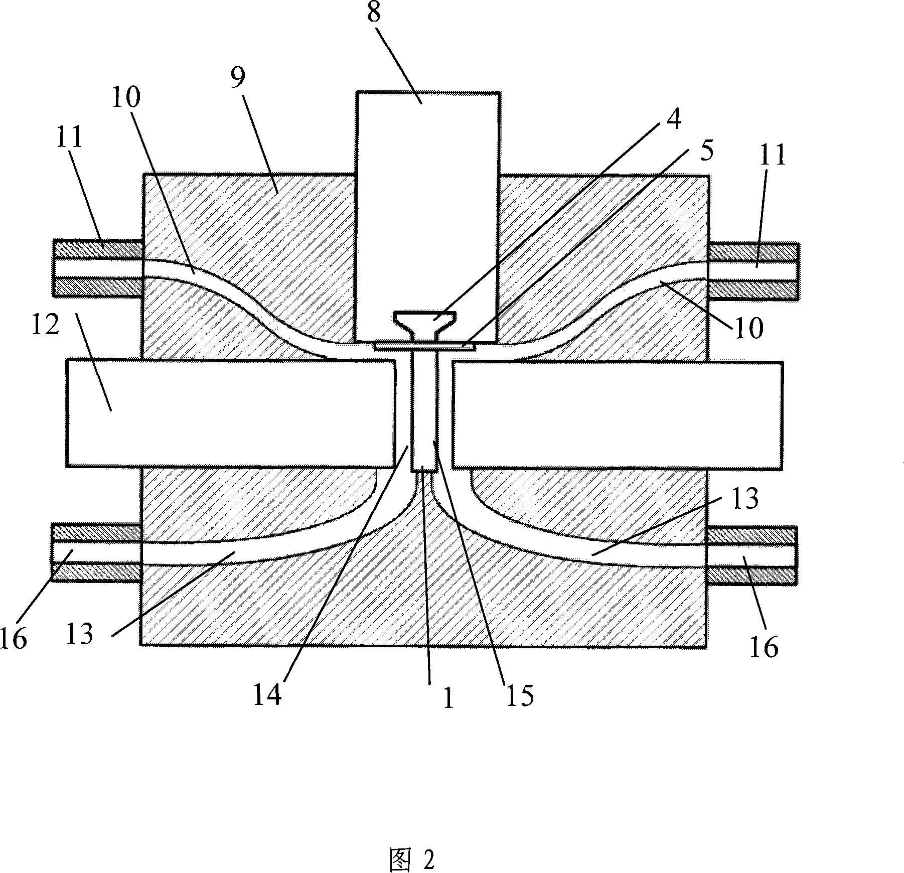
[0033] As shown in Figures 1 and 2, the electrolyte splitting device is included in the fixture 9, and the main part of the fixture 9 is made of insulating materials such as epoxy resin. There are four flow channels extending from the edge to the processing area around the inside of the fixture 9, which correspond to each other, respectively, the electrolyte inflow (outflow) channel 10 and the electrolyte outflow (inflow) channel 13, and the electrolyte inflow (outflow) The ends of the channel 10 and the electrolyte outflow (inflow) channel 13 are connected with four inlet or outlet ports of the electrolyte, and the electrolyte is introduced into the electrolyte inflow (outflow) channel 10 through the inlet or outlet ports of the electrolyte And the electrolyte solution flows out (flows) into the channel 13 .

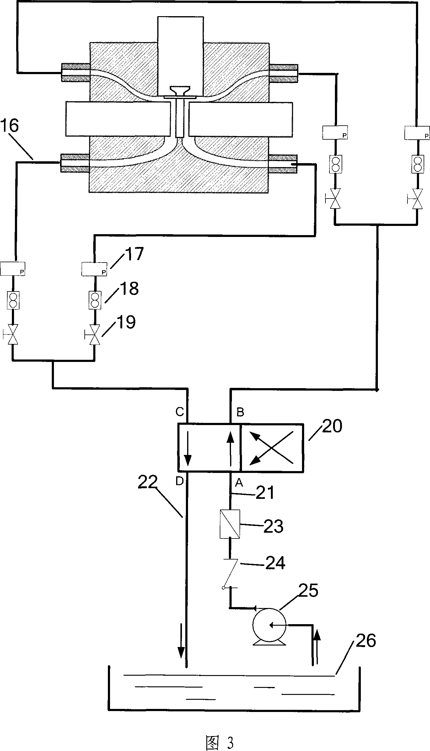
[0034] As shown in Figure 3, it is a schematic diagram of the electrolyte flow equalization and reversing device. Including 17. Pressure gauge, 18. Flow meter, 19. Reg...


PUM


Abstract

The invention relates to an active-control electrolyte flowing method and an electrolyte circulating system in blade processing, and belongs to the field of electrolytic processing technology. The method is characterized in that (1) an entire blade processing region is divided into a blade concave processing region and a blade convex processing region by a blade; and (2) an active shunting method is adopted to divide the channel into two independent channels including an electrolyte channel for blade concave processing and an electrolyte channel for blade convex processing. The electrolyte circulating system is characterized in that four channels are arranged at the periphery inside a tool fixture (9), extending from the edges to the processing regions, and each channel is respectively connected with a flow rate control pipe. The system is also provided with an electrolyte reversing valve (20) to reverse the flowing direction of the electrolyte. The active-control electrolyte flowing method can achieve more stabile flow field for processing the blade, more uniform flow field state for processing different sections of the blade, and better processing accuracy and surface quality.

Description

technical field [0001] The invention relates to an actively controlled electrolyte flow method and an electrolyte circulation system in blade processing, belonging to the technical field of electrolytic processing. Background technique [0002] Electrolytic machining is a special processing technology, which is a processing method that uses the principle of electrochemical anodic dissolution to remove materials. It has the outstanding advantages of fast processing speed, good surface quality, no loss of tools, no restrictions on material strength, toughness, hardness, etc., and no macro cutting force. It has been widely used in aerospace, weapons, automobiles, molds and other industries. . Especially in the manufacturing process of aero-engine blades, blade materials continue to develop in the direction of high strength, high hardness, and high toughness, and the application of new materials such as titanium alloys and high-temperature heat-resistant alloys makes the manufa...

Claims


Application Information

Patent Timeline
IPC IPC(8): B23H3/10
Inventor 朱荻徐正扬曲宁松朱栋
Owner NANJING UNIV OF AERONAUTICS & ASTRONAUTICS
Learn More