Apparatus for preparing S type metallic honeycomb

A technology of metal honeycomb and locking device, applied in muffler device, exhaust device, metal processing equipment, etc., can solve the problems of high rolling requirements and high production cost

Active Publication Date: 2008-08-27
南京亿达高科环保技术有限公司 +1
View PDF1 Cites 24 Cited by
  • Summary
  • Abstract
  • Description
  • Claims
  • Application Information

AI Technical Summary

Problems solved by technology

[0007] The purpose of the present invention is to provide a manufacturing device suitable for S-shaped metal honeycombs of domestic iron-chromium-aluminum flakes, to solve the problems of high rolling requirements and high production costs of iron-chromium-aluminum flakes made of metal honeycombs in the prior art

Method used


Image

  • Apparatus for preparing S type metallic honeycomb
  • Apparatus for preparing S type metallic honeycomb
  • Apparatus for preparing S type metallic honeycomb

Examples


Embodiment Construction

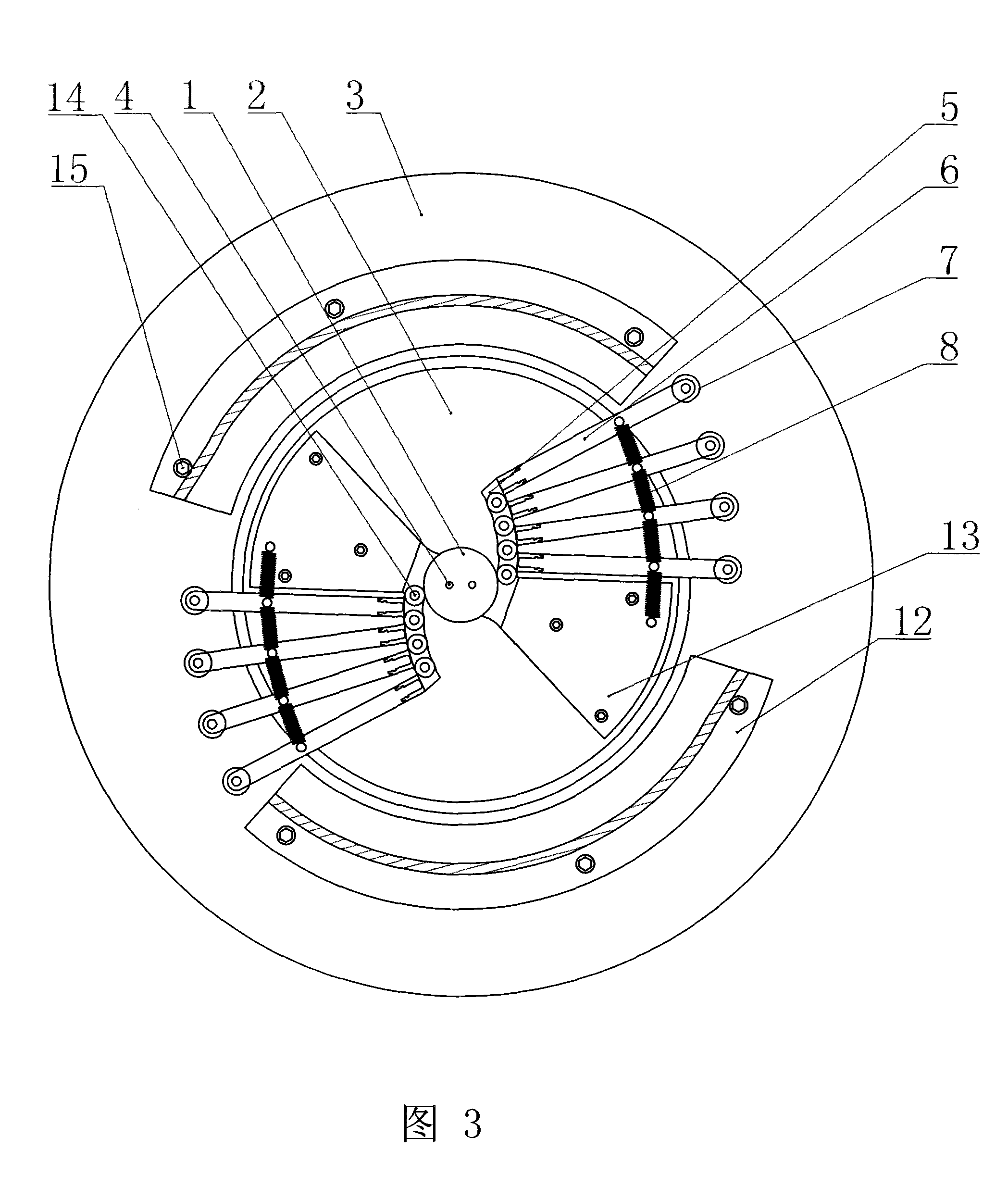
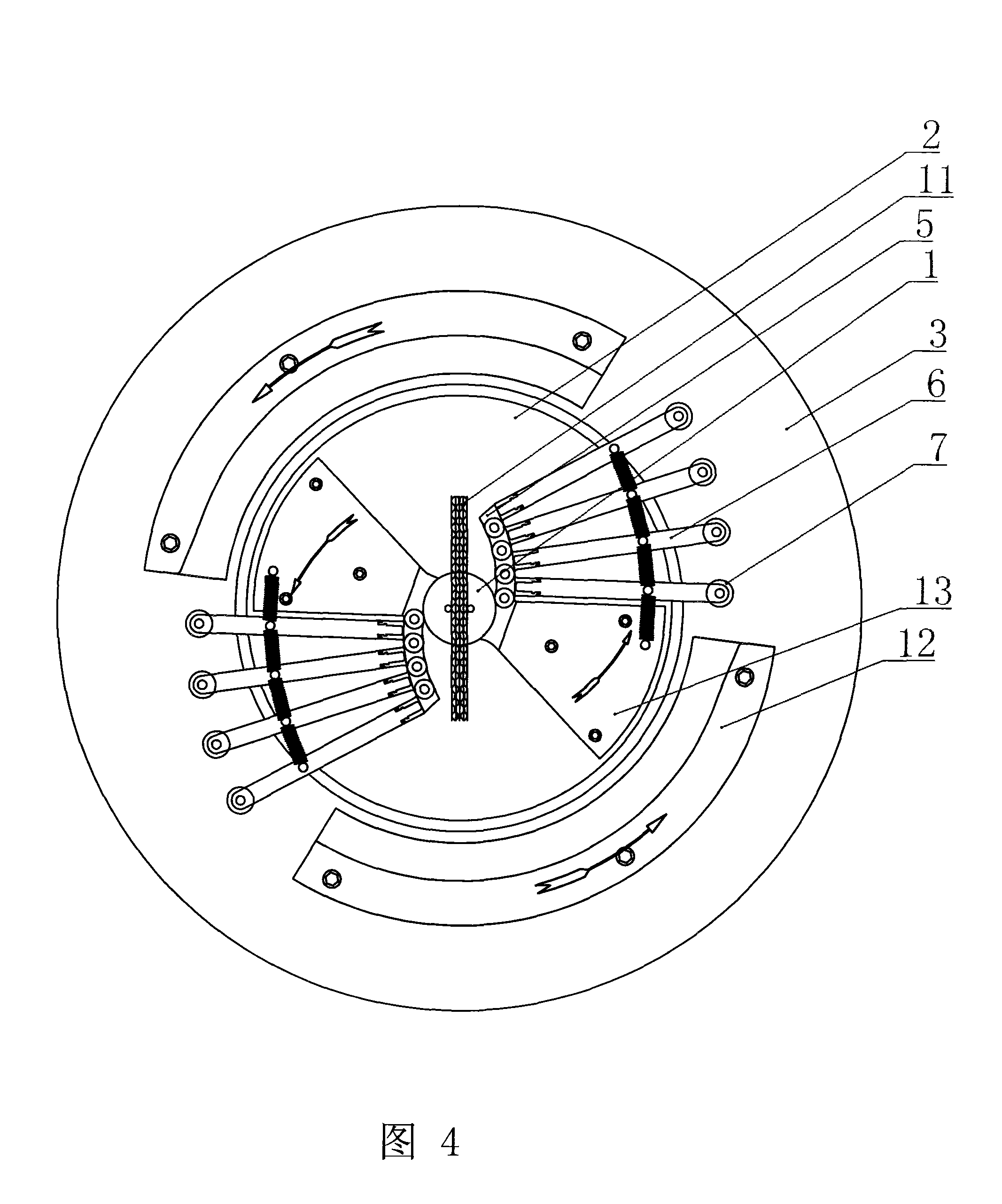
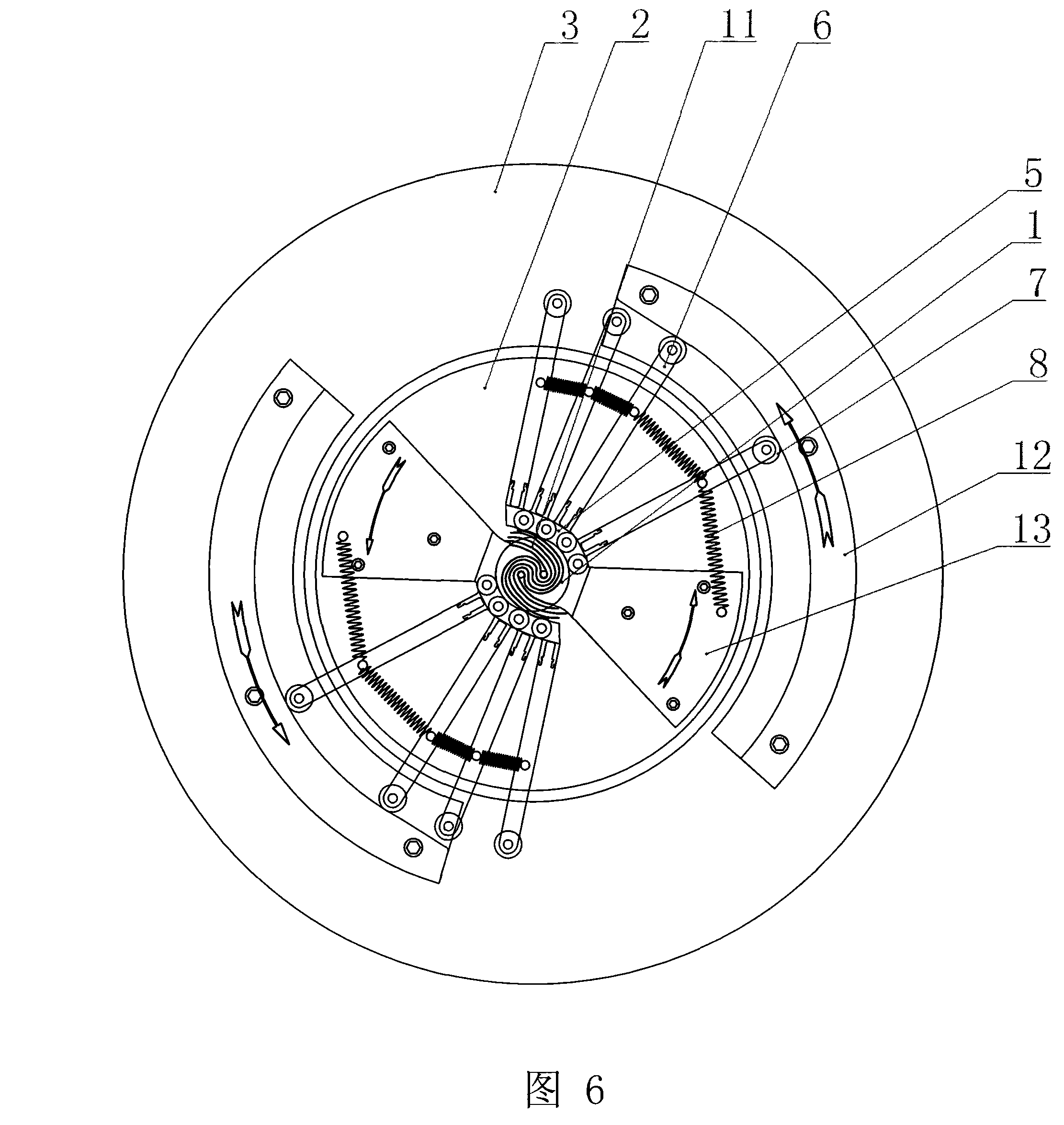
[0019] As shown in Figures 3 to 7, this embodiment of the present invention includes a cylindrical fixed column 1 and two groups of forming sections 5 that can be gradually closed to each other to form a mold, and two coaxial fixed rods are arranged at the top of the fixed column 1 4. The described forming section 5 of every group is made up of five sections, is hinged with pin 14 to become chain structure between every section.

[0020] A mold locking device is connected to the outside of the forming section 5, and the structure of one embodiment of the mold locking device is: the inner end of a radial driving rod 6 is connected to the outside of each section of the forming section 5, and the driving rod The outer end of 6 is equipped with bearing 7, is connected with spring 8 between each adjacent driving rod 6. The fixed column 1 is installed in the axial hole of an inner disc 2 , and an outer disc 3 is arranged on the outer edge of the inner disc 2 . One section at the s...


PUM


Abstract

The invention relates to a device for preparing an S-shaped metal beehive, comprising a fixed pole (1) and two groups of forming sections (5) which can be mutually closed section by section to form a section mould, wherein, two coaxial fixed rods (4) are arranged on the top of the fixed pole (1). The invention is characterized in that: each group of forming sections (5) consist of at least three sections; a chain structure is hinged between each section by utilization of a pin pole; the forming sections (5) can be gradually deformed from a straight line or a curve with small curvature to a curve with large curvature; the two groups of forming sections (5) are closed to form the section mould the cross section of which is round, obround or elliptical. Due to adoption of the technical proposal, the metal stack fixed rods (namely the S-shaped center) are immobile during the rolling process; corrugated tooth profiles can be straightened by the sectional closed section mould during the rotation process even an inner core material piece is slightly longer, and residual tooth profiles can be straightened into flat sheets and then attached to the circumference of an inner core of the beehive; moreover, an S-shaped central tooth profile is always immobile and then can not be deformed, thereby the forming quality and the finished product rate are improved.

Description

technical field [0001] The invention relates to a roll-up device for a metal honeycomb of an engine emission catalytic converter. Background technique [0002] With the increasingly stringent emission regulations, higher technical requirements have been put forward for the metal honeycomb used in exhaust gas catalytic converters. The metal carrier generally consists of a honeycomb core 9 and an outer shell 10 (see Figures 1 and 2). The metal carrier currently produced in my country is basically a spiral honeycomb structure (see Figure 1). This is a product of the 1970s abroad. Due to its poor thermal creep resistance and thermal deformation resistance and poor durability, a large number of them have been S-shaped abroad. The honeycomb structure (see Figure 2) is replaced. The S-shaped structure is the basic structure of the metal carrier because of its reliable durability and good turbulent flow. [0003] Patent CN1078101C discloses a rolling device and method of S-shaped ...

Claims


Application Information

Patent Timeline
Patent Type & Authority Applications(China)
IPC IPC(8): F01N3/28B21D53/00B01J35/04B01D53/92
Inventor 夏琦
Owner 南京亿达高科环保技术有限公司
Why Eureka
Try Eureka