
General-purpose plug socket tools

A jig and plug hole technology, applied in the direction of electrical components, printed circuit manufacturing, printed circuit, etc., can solve the problems that affect the timeliness of plug hole production, insufficient strength of the base material on the jig, and production interruption, so as to ensure the production of products High quality, not easy to contaminate fixtures, easy to maintain and clean

Inactive Publication Date: 2008-08-27
GULTECH WUXI ELECTRONICS CO LTD
View PDF0 Cites 7 Cited by
  • Summary
  • Abstract
  • Description
  • Claims
  • Application Information

AI Technical Summary

Problems solved by technology

[0003] 1. Jigs with different material numbers cannot be shared. Jigs must be made separately according to the material number. After a single material number is produced, the jig needs to be scrapped. The production board cannot be recycled and is difficult to handle. It is not environmentally friendly and the material cost is high
[0004] 2. The production of fixtures needs to be produced by a separate drilling machine, and the production time is long. Generally, the production of a set of fixtures needs to be drilled for 7-10 hours, which affects the timeliness of plug hole production and occupies the drilling mass production machine, affecting normal operation. mass production
[0005] 3. When producing jigs, it is necessary to run the drilling machine for a long time, which will consume a lot of energy such as electricity, air pressure, and vacuuming, as well as corresponding backing plates, aluminum sheets, drill needles and other auxiliary consumables
[0006] 4. The production of jigs requires a dedicated manpower cost per shift
[0007] 5. If the density of holes in the board is high, because the apertures on the jig are enlarged, the unintersecting holes on the PCB are drilled into jigs, and many holes will intersect with each other, resulting in the strength of the base material on the jig. Insufficient, the chip is easy to drop during the production process, which affects the product quality, and even the chip is too large to stick to the PCB. During the exposure process, the glass of the exposure machine is broken, causing production interruption, and spending a lot of money to repurchase the glass
[0008] 6. Due to the limited thickness of the drilled jig and the limited diameter of the air hole, when the plug hole is too full, ink is likely to accumulate in the air hole, contaminate the jig, and the dirt on the jig will stick to the subsequent production board, affecting the product quality

Method used


Image

  • General-purpose plug socket tools

Examples


Embodiment Construction

[0019] The present invention will be further described below in conjunction with the embodiments in the accompanying drawings:

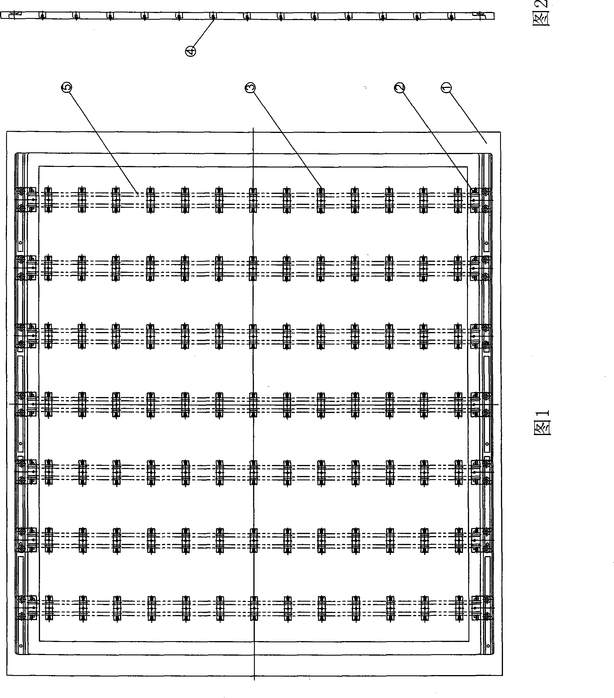
[0020] The present invention is mainly composed of a base plate 1 , a sliding block 2 , a PIN nail fixing block 3 , a PIN needle 4 , and a sliding rail 5 .

[0021] The present invention mainly adopts the sliding block 2 to be mounted on the bottom plate 1, and the sliding rail 5 to be mounted on the sliding block 2. All the components on the sliding rail 5 will move in the X direction together with the sliding rail 5 along with the sliding block 2. Block 2 is provided with holes. The PIN nail fixing block 3 is mounted on the sliding rail 5 and can move in the Y direction along the sliding rail 5, and the PIN nail fixing block 3 is provided with a hole. The PIN needle 4 is fixed on the PIN nail fixing block 3. The position of the PIN needle 4 is determined by the slider 2 and the PIN nail fixing block 3 to determine its coordinates. The PIN needle 4...


PUM


Abstract

The invention relates to a multi-purpose hole plugging fixture, which is especially used for HDI PCB soldering resistant hole plugging processing, HDI PCB soldering resistant printing and plugging processing, HDI PCB soldering resistant printing surface ink processing and HDI board sucore buried hole plug resin. The invention mainly adopts a sliding block installed on the bottom plate, a slide rail is arranged on the sliding block, and all parts on the slide rail together with the slide rail are moved in X direction along with the sliding block. A PIN nail fixed block is arranged on the slide rail, and can be moved in Y direction along the slide rail. A PIN nail is fixed on the PIN nail fixed block, the coordinate of the position of the movement of the PIN nail is determined by the sliding block and the PIN nail fixed block together, and the PIN nail plays the role of printing or sheet material supporting during the hole plugging process. The multi-purpose hole plugging fixture can be used unlimited times, therefore, the material cost and the disposal cost for fixture treatment can be saved; the energy can be saved, and a risk of chip falling cannot be caused; the fixture is uneasy to be polluted, the servicing is clean and simple, and the product quality can be guaranteed.

Description

technical field [0001] The invention relates to a universal plug hole jig, in particular to the process of HDI PCB anti-soldering plug hole manufacturing process, the process of HDI PCB anti-soldering continuous plug tape printing, the process of HDI PCB anti-soldering printing surface ink and the sucoreburied hole of HDI board Plug resin. Background technique [0002] In the prior art, a substrate with a thickness of about 1.5mm is usually used, which is cut to the same size as the produced board. The CAM designs the corresponding drilling program according to the PCB hole position of the corresponding material number, and uses a mechanical drilling machine. For processing, a hole with a diameter of 60 mil is drilled at the coordinates of the hole where the hole needs to be plugged, and then the copper foil on the surface is etched away. There are problems with the fixture of this structure: [0003] 1. Fixtures of different material numbers cannot be shared. The fixtures...

Claims


Application Information

Patent Timeline
Patent Type & Authority Applications(China)
IPC IPC(8): H05K3/00
Inventor 龚鸿琳
Owner GULTECH WUXI ELECTRONICS CO LTD
Learn More