Method for forming cross wall of plasma display panel

A display panel, plasma technology, applied in the manufacture of discharge tubes/lamps, the manufacture of ships or lead wires, discharge tubes, etc., can solve the problems of difficulty in forming address electrodes and application, and achieve full panel reliability. Effect

Inactive Publication Date: 2008-08-27
FUJITSU HITACHI PLASMA DISPLAY LTD
View PDF1 Cites 0 Cited by
  • Summary
  • Abstract
  • Description
  • Claims
  • Application Information

AI Technical Summary

Problems solved by technology

That is, since the address electrodes are formed after the barrier ribs are formed, it is difficult to form the address electrodes
When forming a so-called box-shaped partition wall having not only vertical partition walls but also horizontal partition walls, it is necessary to either provide through holes in the horizontal partition walls or to provide address electrodes over the horizontal partition walls. From a reliability point of view, it is very difficult to apply at this stage

Method used


Image

  • Method for forming cross wall of plasma display panel
  • Method for forming cross wall of plasma display panel
  • Method for forming cross wall of plasma display panel

Examples


Embodiment Construction

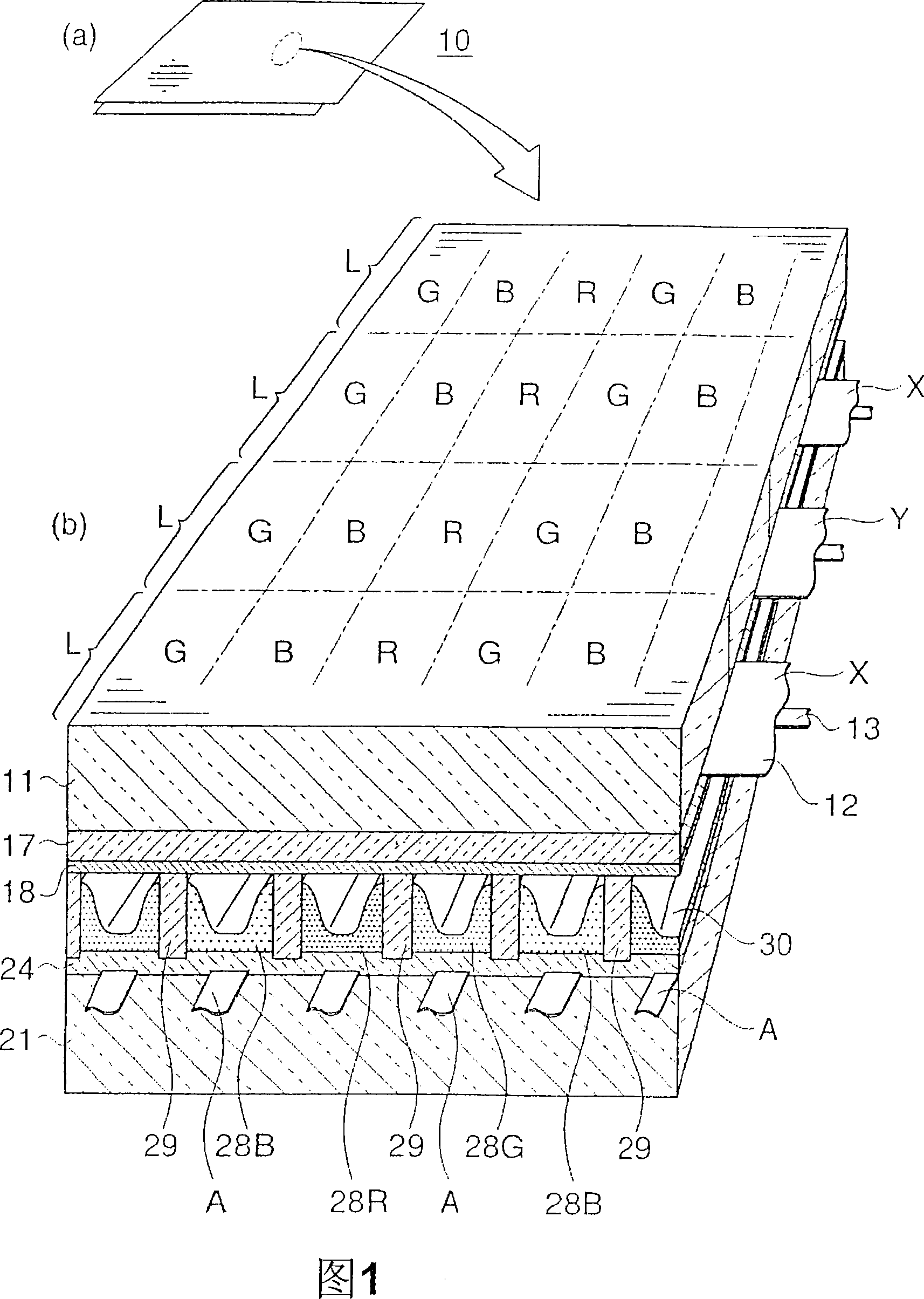
[0034] In the present invention, first, a dry film to be a dielectric layer is formed on a substrate. The substrate includes substrates such as glass, quartz, ceramics, and the like, and substrates on which desired components such as electrodes are formed.

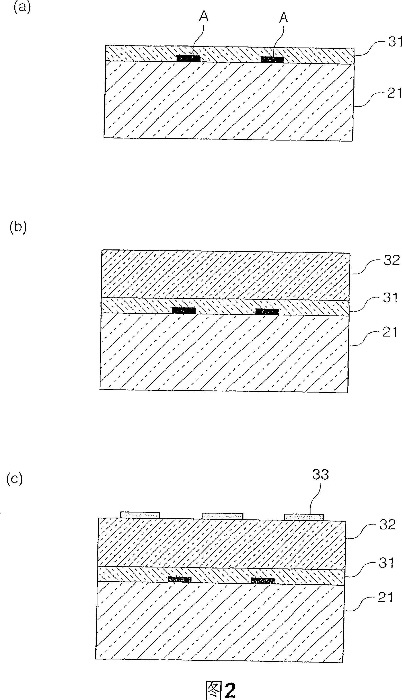
[0035] The dry film used as the dielectric layer can be formed by, for example, applying a low-melting-point glass paste on a substrate by a well-known method such as a screen printing method or a paste coating method and drying it. The low melting point glass paste can be formed using various paste materials known in the art. However, in the present invention, the dry film is preferably formed of a material containing a resin in an amount capable of imparting adhesion to a glass sheet and sandblast resistance after drying.

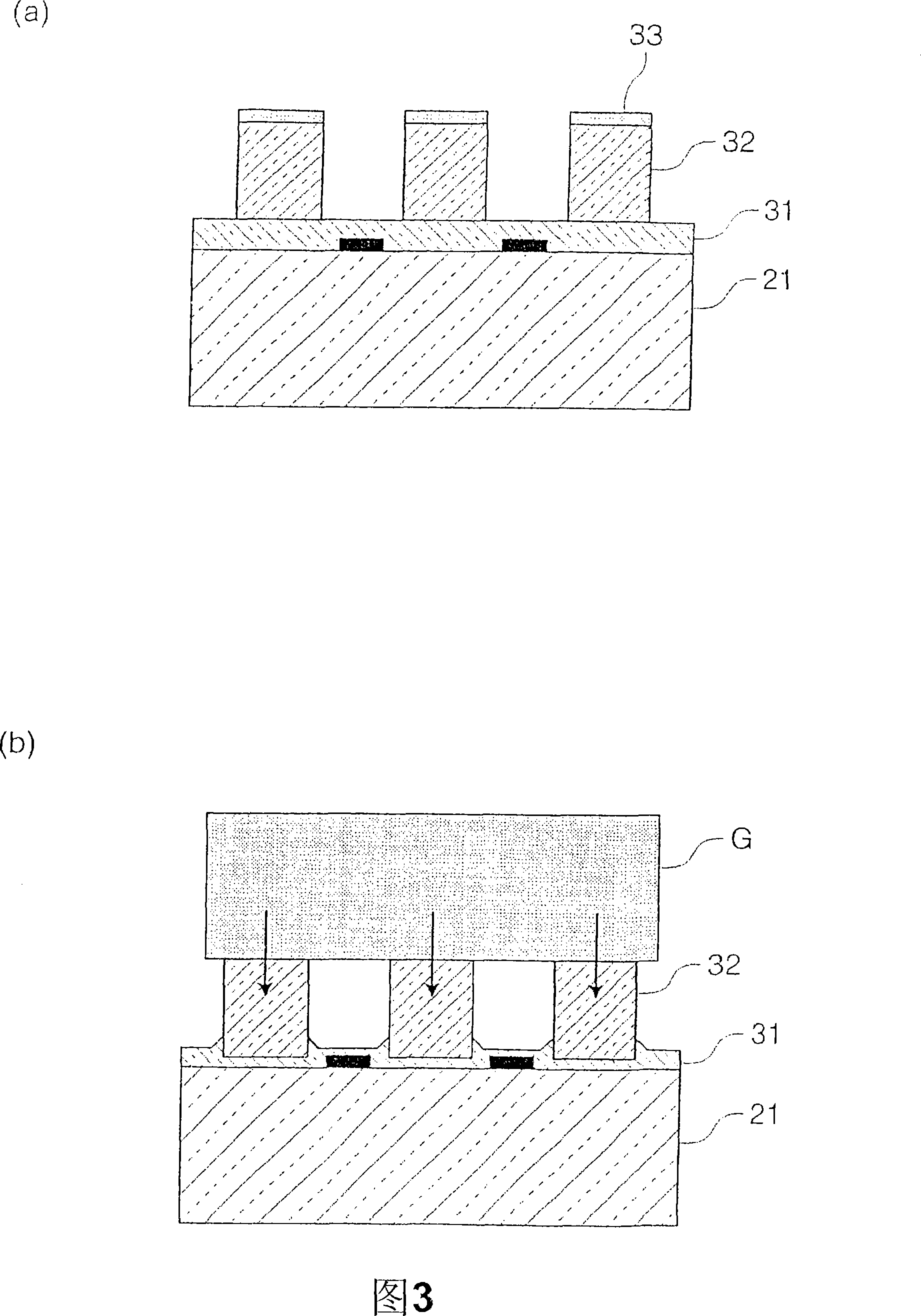
[0036] Alternatively, the dry film can also be formed by pasting a pre-made adhesive sheet containing a resin in an amount capable of imparting adhesiveness to a glass sheet and sandblasting resistance on...


PUM


Abstract

A partition wall is formed using a glass sheet, thereby lowering cost of partition wall formation and facilitating formation of partition wall and electrode. Dry film (31) convertible to a dielectric layer by firing is provided on substrate (21). Glass sheet (32) with a thickness corresponding to the height of partition wall to be formed is fixed on the dry film. Resist pattern (33) corresponding to the morphology of partition wall is provided on the glass sheet. Unwanted portion of the glass sheet is sandblasted off, thereby forming the glass sheet into a configuration of partition wall. The dry film is fired at a temperature not higher than the softening points of the substrate and glass sheet so as to attain bonding of the substrate with the glass sheet by means of a dielectric layer being a fired dry film. Thus, formation of a partition wall is accomplished.

Description

Technical field [0001] The present invention relates to a method of forming a partition wall of a plasma display panel (PDP), and more specifically, to a method of forming a partition wall mainly applied to an AC-driven 3-electrode surface discharge type PDP. Background technique [0002] As a conventional PDP, an AC-driven three-electrode surface discharge type PDP is known. Regarding this PDP, a plurality of display electrodes capable of surface discharge are provided on the inner surface of one substrate (for example, the substrate on the front side or the display side) along the horizontal direction, and the inner surface of the other substrate (for example, the substrate on the back side) is in contact with each other. A plurality of address electrodes for selecting light-emitting cells are arranged in the direction where the display electrodes intersect, and the intersection of the display electrodes and the address electrodes is used as a unit (unit light-emitting area). O...

Claims


Application Information

Patent Timeline
Patent Type & Authority Applications(China)
IPC IPC(8): H01J9/02H01J11/02H01J9/24H01J17/49
Inventor 金江达利藤永昭弘
Owner FUJITSU HITACHI PLASMA DISPLAY LTD
Why Eureka
Try Eureka