
Patsnap Eureka
For R&D, Patsnap Eureka makes reading and utilizing patents & technical documents easy.
Patsnap Eureka AIR
Designed for self-driven R&D workflows. Generate viable solutions, solve complex R&D challenges, empower your innovation with AI.

Patsnap Eureka Materials
Designed for material experts only. Revolutionize your material R&D, from search, analyze, to developing new materials.

TechResearch
Generate reliable direction feasibility study reports for your R&D in just a few steps.

TechSeek
Discover and master advanced knowledge NOW. Basics, ideas, possibilities, all at once.

TechMind
As an expert in R&D Theories, TechMind can generates customized viable solutions instantly.

TechRisk
Analyze your overall solution with one click, know your potential R&D risks in advance.

TechMonitor
Get weekly tech updates, stay abreast of the latest tech innovations and key insights.
Electrochemical cell stack
A battery stack and electrochemical technology, applied in electrochemical generators, fuel cells, solid electrolyte fuel cells, etc., can solve problems such as inapplicable spring systems
- Summary
- Abstract
- Description
- Claims
- Application Information
AI Technical Summary
Problems solved by technology
Method used
Image

Examples
Embodiment Construction
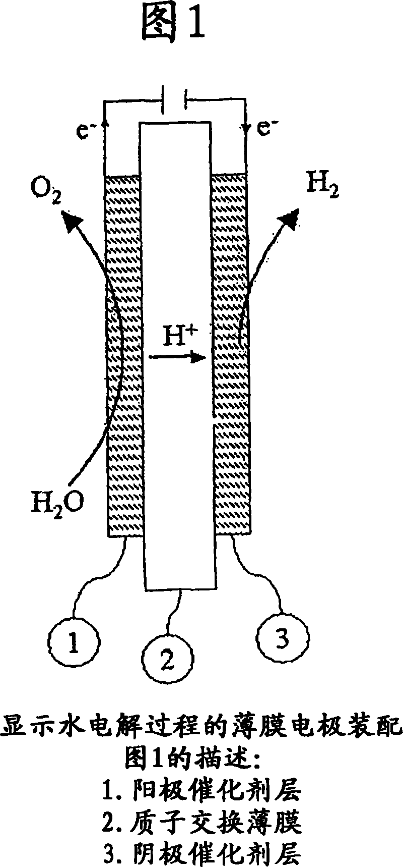
[0049] Figure 1 illustrates the water electrolysis process in a PEM cell, where water is supplied to the anode side 1 and, under an applied electric potential field, becomes split into oxygen, protons and electrons. The proton migrates to the cathode side 3 where it recombines with an electron to form hydrogen gas.
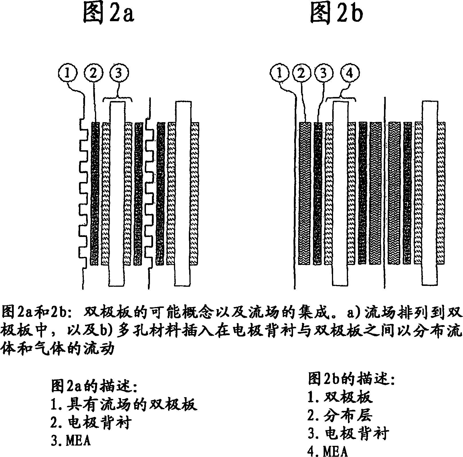
[0050] Figures 2a and 2b show two typical concepts where a) the flow pattern is integrated into the bipolar plate or b) the porous layer is inserted between the bipolar plate and the electrode backing. This porous layer must then provide electrical contact between the bipolar plate and the electrode backing, and it must provide fluid flow into and out of the battery compartment. A gasket is placed around the electrode backing area between the membrane and the bipolar plate (not shown in Figure 2). Fluid flow to and from the cell is typically through gaskets and channel arrangements within the bipolar plates.
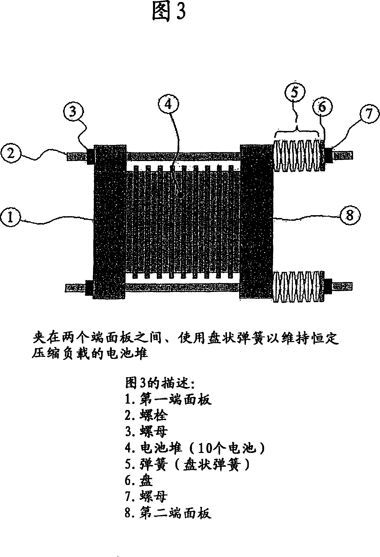
[0051] FIG. 3 shows a battery stack 4 of 10 cells co...
PUM
 Abstract
Description
Claims
Application Information
 - R&D Engineer
- R&D Manager
- IP Professional
- Industry Leading Data Capabilities
- Powerful AI technology
- Patent DNA Extraction
Browse by: Latest US Patents, China's latest patents, Technical Efficacy Thesaurus, Application Domain, Technology Topic, Popular Technical Reports.
© 2024 PatSnap. All rights reserved.Legal|Privacy policy|Modern Slavery Act Transparency Statement|Sitemap|About US| Contact US: help@patsnap.com