
Development method of microvesicle generators

A technology of microbubble generator and computing area, applied in the development field of microbubble generating device, can solve the problems of cumbersome test and testing method, long design and manufacturing cycle, unreasonable, etc. The effect of development prospects

Inactive Publication Date: 2011-02-16
KUNMING UNIV OF SCI & TECH
View PDF0 Cites 0 Cited by
  • Summary
  • Abstract
  • Description
  • Claims
  • Application Information

AI Technical Summary

Problems solved by technology

At present, the microbubble generator is mainly designed by empirical design and physical experiment means, which has the disadvantages of long design and manufacturing cycle, high processing cost, and cumbersome test methods. It is neither economical nor reasonable, and does not meet the development requirements of microbubble generators.

Method used


Image

  • Development method of microvesicle generators
  • Development method of microvesicle generators
  • Development method of microvesicle generators

Examples


Embodiment Construction

[0023] Typical embodiments of the present invention will be described in further detail below in conjunction with the accompanying drawings, and the following embodiments are used to illustrate the present invention.

[0024] The method of the present invention adopts CAD software, CFD software and the method that experiment combines to develop and design the microbubble generator. Dynamic diffusion produces uniform and tiny bubbles to meet the needs of microbubble flotation. In the designed microbubble generator, the airflow is broken into microbubbles, which can effectively solve the problem of easy blockage of the microbubble generator. Referring to the accompanying drawings, the jet microbubble generator will be taken as an example for specific description below.

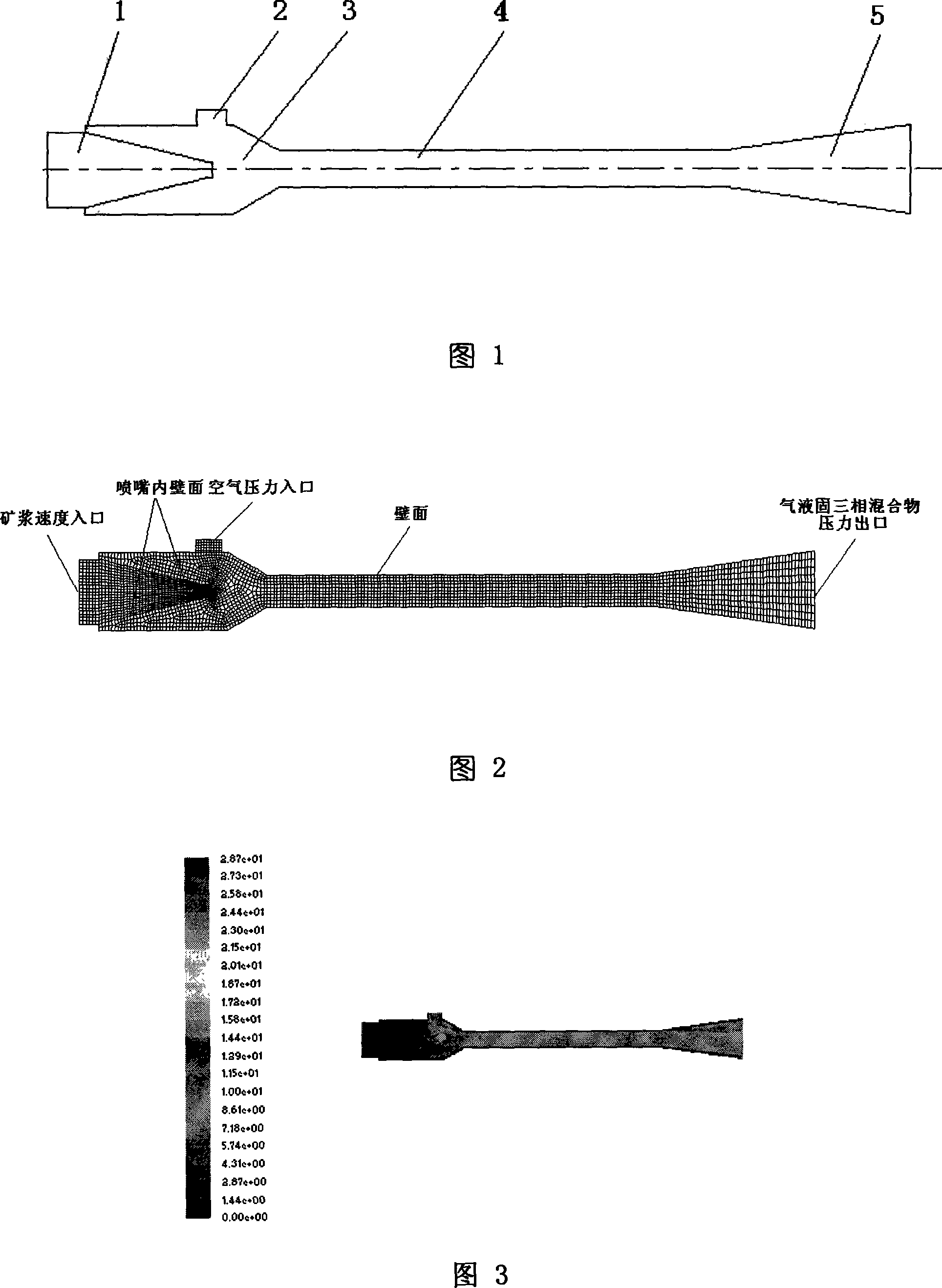
[0025] figure 1 is the calculation area graph of the example, as figure 1 As shown, the CAD software is used to draw, and the names of the various parts are as follows: 1-nozzle, 2-suction pipe, 3-mixing cham...


PUM


Abstract

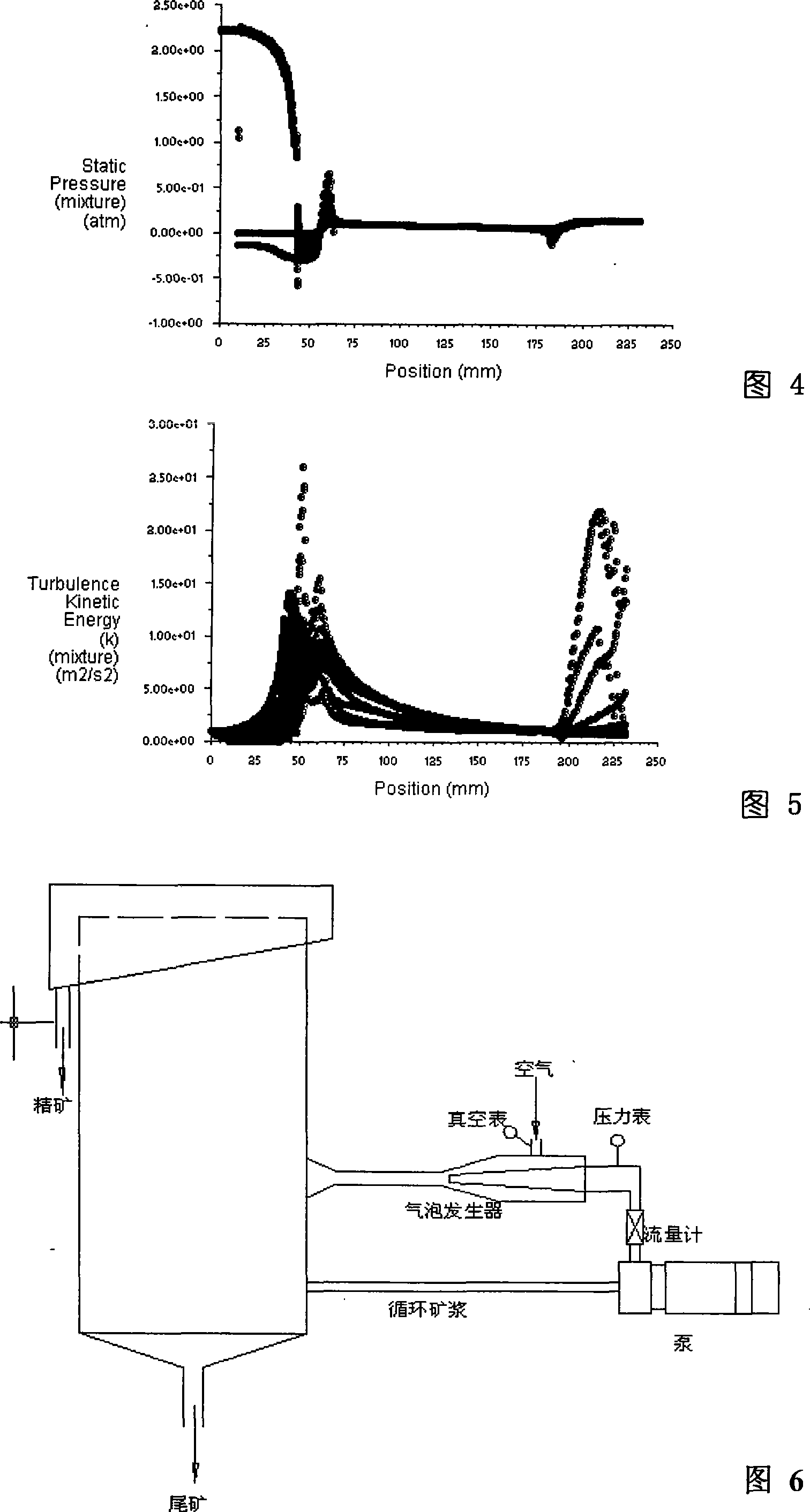
The invention discloses a method for developing a microbubble generator and the application thereof. The method includes the following steps: (1) designing the structure of the microbubble generator by using the CAD software; (2) establishing a finite volume computation model of the microbubble generator, and performing grid division of the model and setting boundary conditions of computation regions; (3) performing numerical computation of the computation regions of the model by using CFD software equation solver; (4) calculating parameters such as velocity field, pressure field and turbulent energy distribution; (5) correcting structural dimensions of the microbubble generator and analyzing various work conditions of the microbubble generator; and (6) manufacturing a physical prototype of the microbubble generator, carrying out physical experiments to verify the correctness of the method. The method can reduce the development cost, improve the design reliability, shorten the development period, and integrate computer-based numerical simulation and physical experiment. The inventive method is also used for the development of other fluid mechanisms.

Description

technical field [0001] The invention relates to the technical field of microbubble flotation in mineral processing, in particular to a development method and application of a microbubble generating device. Background technique [0002] The microbubble generator is an important device for generating microbubbles and a key component in the microbubble flotation system. In microbubble flotation, one of its important key technologies is how to obtain microbubbles with reasonable size, quantity, distribution and flow pattern. In addition, the blockage of the microbubble generator has always been the bottleneck restricting the development of microbubble flotation technology. These are directly related to the characteristics of the flow field in the microbubble generator. At present, the microbubble generator is mainly designed by empirical design and physical experiment means, which has the disadvantages of long design and manufacturing cycle, high processing cost, and cumbersom...

Claims


Application Information

Patent Timeline
Patent Type & Authority Patents(China)
IPC IPC(8): B03D1/14B01F5/02B01F3/04G06F17/50
Inventor 李浙昆张宗华谢军郭晟李富玉何邦贵
Owner KUNMING UNIV OF SCI & TECH
Learn More