Topological magnetic integrated converter suitable for LLC resonance series
A resonant converter, the technology of the converter is applied in the conversion equipment with intermediate conversion to AC, DC power input is converted to DC power output, instruments, etc. and other problems, to achieve the effect of reducing volume, easy leakage inductance, and improving power density
- Summary
- Abstract
- Description
- Claims
- Application Information
AI Technical Summary
Problems solved by technology
Method used
Image

Examples
Embodiment 1
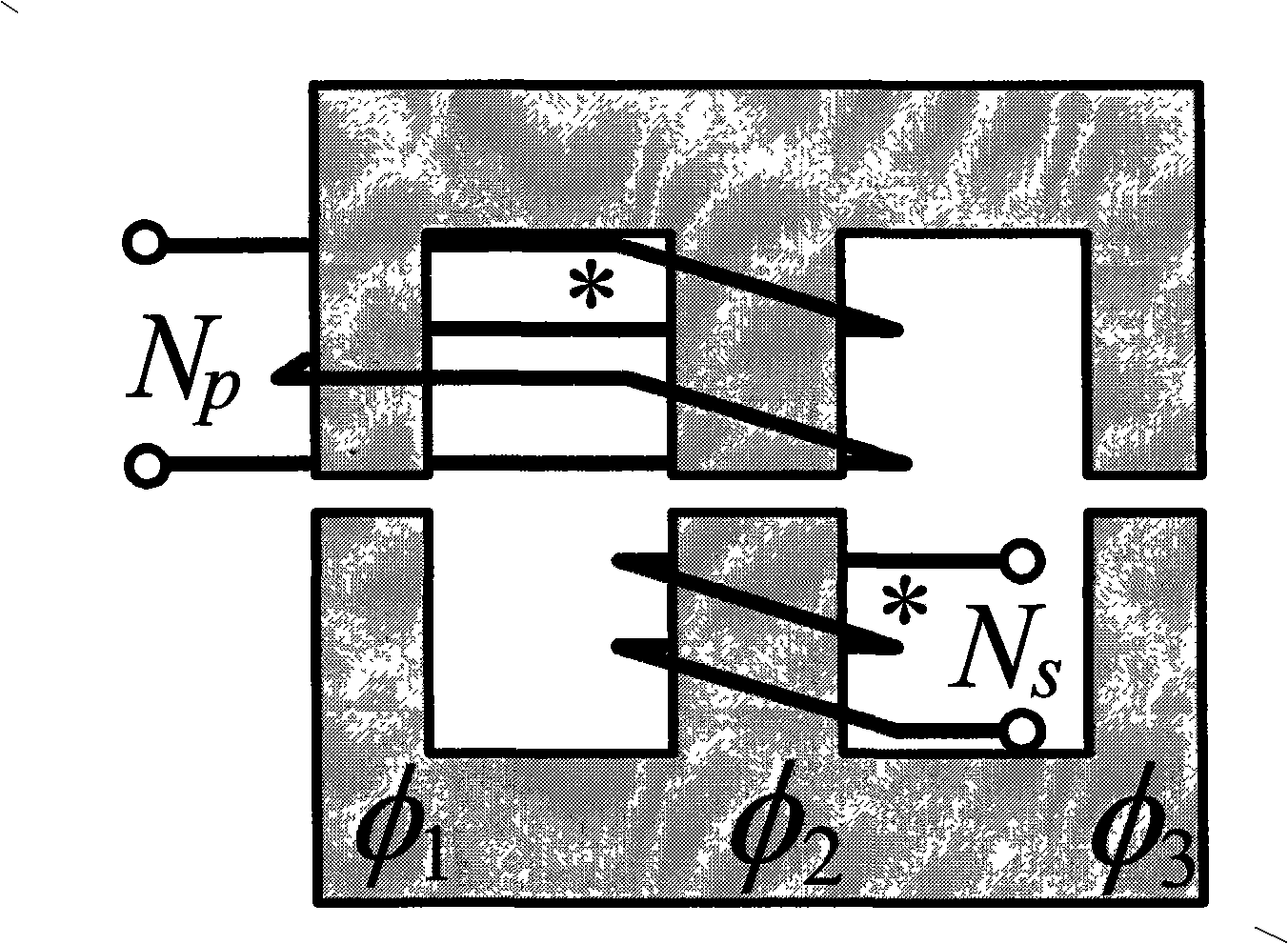
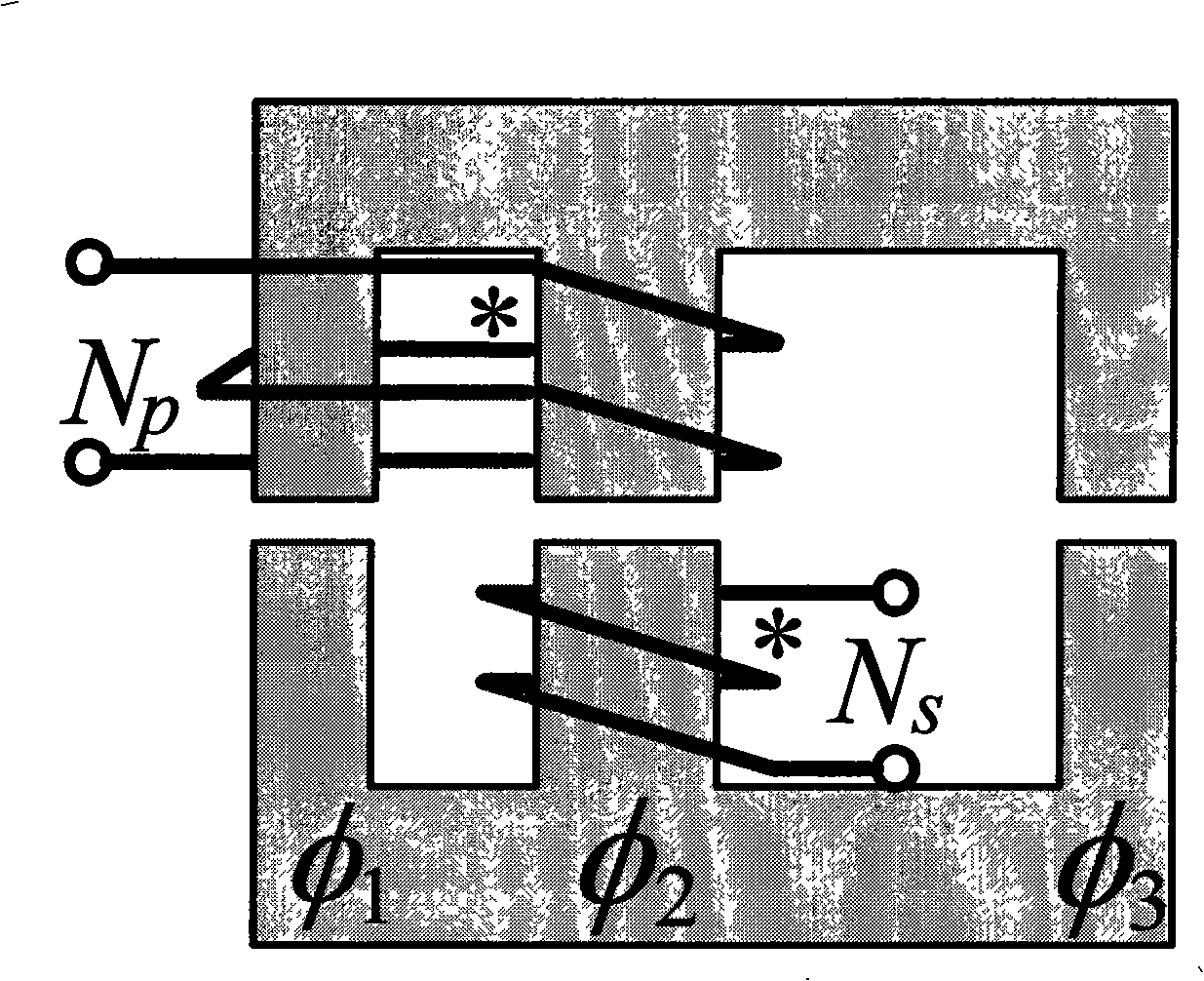
[0033]Referring to FIG. 6 , it is a schematic diagram of applying the integrated magnetic part of FIG. 2 to a half-bridge LLC resonant converter. Including DC power supply, LLC resonant converter primary circuit, secondary rectification filter circuit and EE integrated magnetic parts, it integrates the transformer and resonant inductor in the traditional LLC resonant converter to obtain integrated magnetic parts. The iron core material can be selected from various ferromagnetic materials such as ferrite, microcrystalline, ultrafine crystal, permalloy, etc. In addition, the distance between the two windings bypassed by the primary side can be reduced by customizing the magnetic core, and the magnetic column where the winding is located It can be changed flexibly, and the winding can be realized by using planar winding or wound winding.
[0034] The half-bridge LLC resonant converter includes a DC power supply (1), a primary side circuit (2) of the LLC resonant converter, and a ...
Embodiment 2
[0036] Referring to FIG. 7 , it is a schematic diagram of applying the integrated magnetic part of FIG. 2 to a full-bridge LLC resonant converter. Among them, when the full-bridge LLC resonantly transmits power to the secondary side, the primary winding (N p ) The current inflow point is the terminal with the same name, which is connected to the negative terminal of the resonant capacitor, and the outflow point is connected to the main power switch tube Q 1 source and Q 2 The connection point of the drain, the two terminals of the secondary winding are connected to the midpoint of the full-bridge rectifier, and the outflow point is connected to the main power switch tube Q 1 source and Q 2 The connection point of the drain, the two terminals of the secondary winding are connected to the midpoint of the full-bridge rectifier.
Embodiment 3
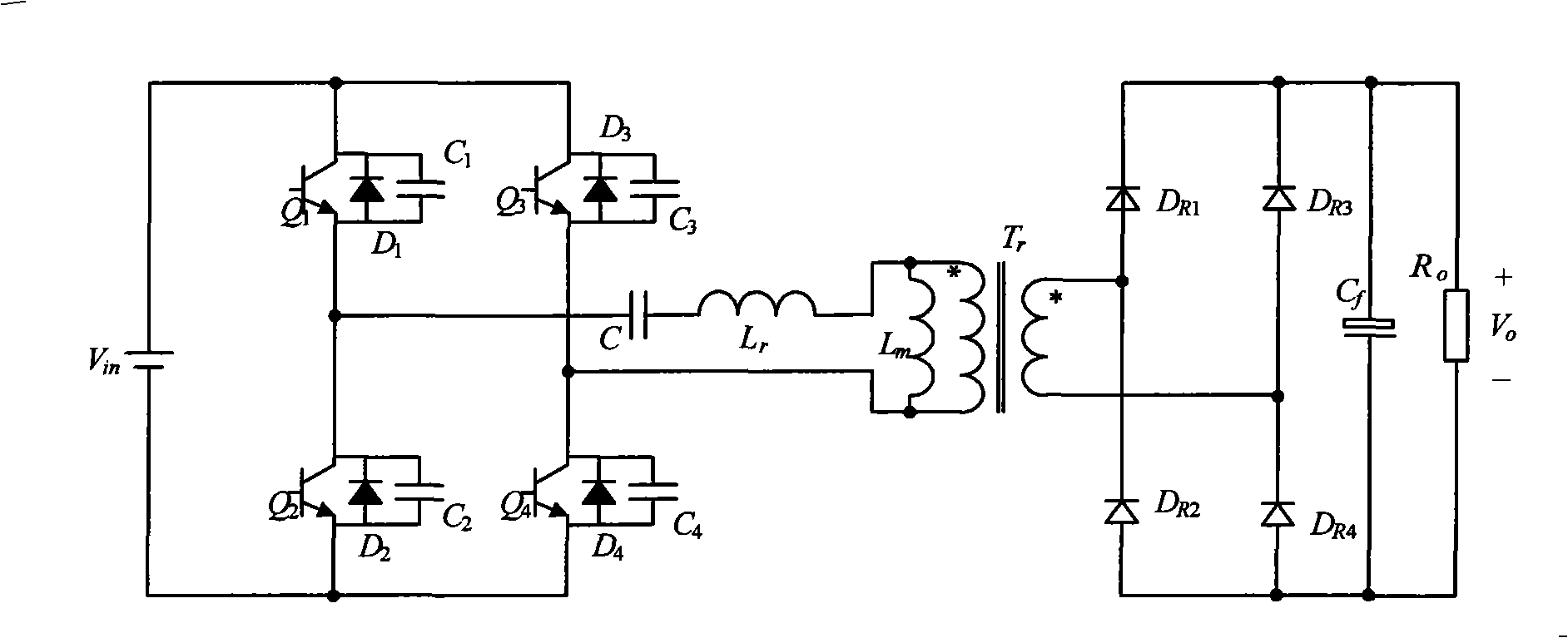
[0038] Referring to FIG. 8 , it is a schematic diagram of applying the integrated magnetic parts of FIG. 2 to a composite full-bridge three-level LLC resonant converter. Among them, when the composite full-bridge three-level LLC resonance transmits power to the secondary side, the primary winding (N p ) The current inflow point is the terminal with the same name, which is connected to the negative terminal of the resonant capacitor, and the outflow point is connected to the main power switch tube Q 5 source and Q 6 The connection point of the drain, the two terminals of the secondary winding are connected to the midpoint of the full-bridge rectifier.
PUM
 Abstract
Description
Claims
Application Information