Full-automatic eddy current sensor dynamic/ static checking instrument

An eddy current sensor and static calibration technology, which is applied in the field of measurement, can solve the problems of increased workload of testers, single function, and long time required for sensor calibration to be sent for calibration, etc., to improve data collection and summary work Efficiency, accuracy of verification results are improved, and test record output is intuitive

Inactive Publication Date: 2008-09-10
上海瑞视仪表电子有限公司
View PDF0 Cites 24 Cited by
  • Summary
  • Abstract
  • Description
  • Claims
  • Application Information

AI Technical Summary

Problems solved by technology

[0008] Due to the working characteristics of the eddy current sensor, the vast majority of users cannot calibrate it on site (referring to the installation site of the user's mechanical equipment), and can only disassemble it and send it to a special laboratory or instrument calibration. It takes a long time for sensor calibration to be sent to the laboratory or sensor manufacturer for inspection and calibration. For some large units or users who have installed multiple eddy current sensors, this is a very time-consuming and laborious task. , costly work, and cannot meet the time requirements for quick maintenance or breakdown repair, which brings hidden dangers to the safe and stable operation of large equipment or complex machinery
[0009] At the same time, due to the differe

Method used


Image

  • Full-automatic eddy current sensor dynamic/ static checking instrument
  • Full-automatic eddy current sensor dynamic/ static checking instrument
  • Full-automatic eddy current sensor dynamic/ static checking instrument

Examples


Embodiment Construction

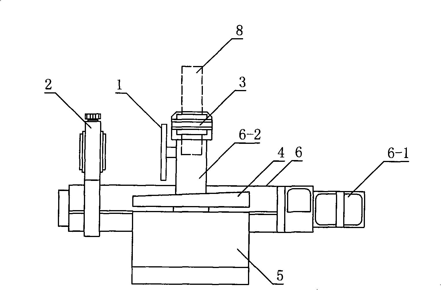
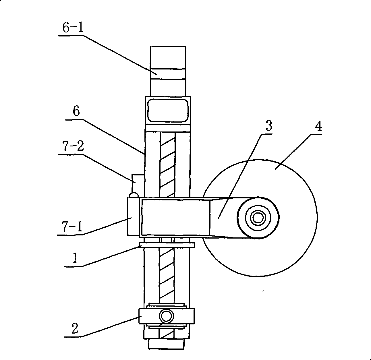
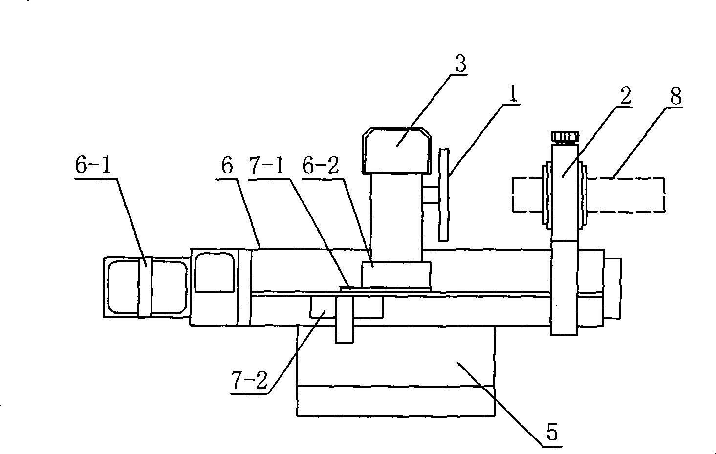
[0065] The present invention will be further described below in conjunction with the accompanying drawings.

[0066] Figure 1 to Figure 3 Among them, the present invention includes a static test unit composed of a static calibration test piece disk 1 and a static calibration probe mounting bracket 2, a dynamic testing unit composed of a dynamic calibration probe mounting bracket 3, a dynamic swash plate 4, and a dynamic swash plate drive motor 5. Unit, its inventive point is that a linear module 6 driven by a stepping motor 6-1 is set, and a movable guide rail extension frame 6-2 driven by it is set on the linear module, and the guide rail extension frame and The linear module is provided with a positioning stopper 7-1 and a non-mechanical contact positioning switch 7-2; The static calibration probe mounting bracket 1; the dynamic calibration probe mounting bracket 3 is set on the guide rail extension frame 6-2, and the dynamic swash plate 4 and its main Drive motor 5.

[0...


PUM


Abstract

The invention provides a completely automatic eddy current sensor dynamic/static checking instrument, belonging to the measurement field. The completely automatic eddy current sensor dynamic/static checking instrument comprises a static testing disc, a static checking bracket, a dynamic checking bracket, a dynamic bias disc, a main driving motor, and a CPU and is characterized in that a linear module group with a movable guide rail extending frame is provided; the guide rail extending frame and the linear module group are provided with a positioning retaining block and a non-mechanical-contact type positioning switch; the guide rail extending frame is provided with the static testing disc; the disc surface of the checking instrument is provided with the static checking bracket; the guide rail extending frame is provided with the dynamic checking bracket; the dynamic bias disc and the main driving motor are arranged below the dynamic checking bracket; the CPU is connected with a stepping motor by a stepping motor driver and is connected with the main driving motor by a main motor driver at the same time; the non-mechanical-contact type positioning switch is connected with the stepping motor driver by a stepping motor control circuit; a probe is connected with a periphery function extending interface circuit of the CPU by a signal detection sampling circuit. The completely automatic eddy current sensor dynamic or static checking instrument is suitable for the dynamic and static checking of eddy current sensors.

Description

technical field [0001] The invention belongs to the technical field of measurement, and in particular relates to a calibration device for an eddy current sensor. Background technique [0002] The important role of sensor technology in social development With the rapid development of science and technology, the testing and control technology of non-physical quantities has been more and more widely used in aerospace, aviation, transportation, metallurgy, machinery manufacturing, petrochemical, light industry, Technical fields such as technical supervision and testing are gradually being introduced into people's daily life. [0003] The eddy current sensor adopts the principle of induced eddy current. When the coil with high frequency current is close to the measured metal, the high frequency electromagnetic field generated by the high frequency current on the coil will generate an induced current on the metal surface, which is called electromagnetically. It is eddy current. ...

Claims


Application Information

Patent Timeline
IPC IPC(8): G01D21/00G01D18/00G01M19/00G01M99/00
Inventor 徐健马效峰
Owner 上海瑞视仪表电子有限公司
Why Eureka
Try Eureka