Engine oil bottom shell

A technology of engine oil and oil pan, which is applied in the direction of engine components, machine/engine, engine lubrication, etc., to achieve the effect of reducing assembly processes, increasing costs, and reducing costs

Inactive Publication Date: 2008-09-17
CHERY AUTOMOBILE CO LTD
View PDF0 Cites 9 Cited by
  • Summary
  • Abstract
  • Description
  • Claims
  • Application Information

AI Technical Summary

Problems solved by technology

[0005] The technical problem to be solved by the present invention is to provide an engine oil pan with high strength, high noise reduction, favorable layout of the whole machine and reasonable structure in order to make up for the deficiencies of the existing engine oil pan.

Method used


Image

  • Engine oil bottom shell
  • Engine oil bottom shell
  • Engine oil bottom shell

Examples


Embodiment 1

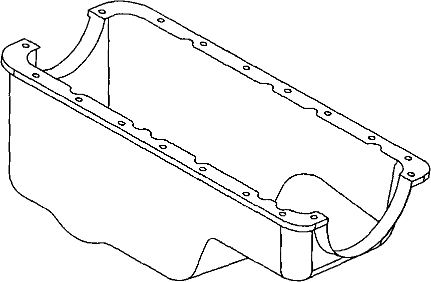
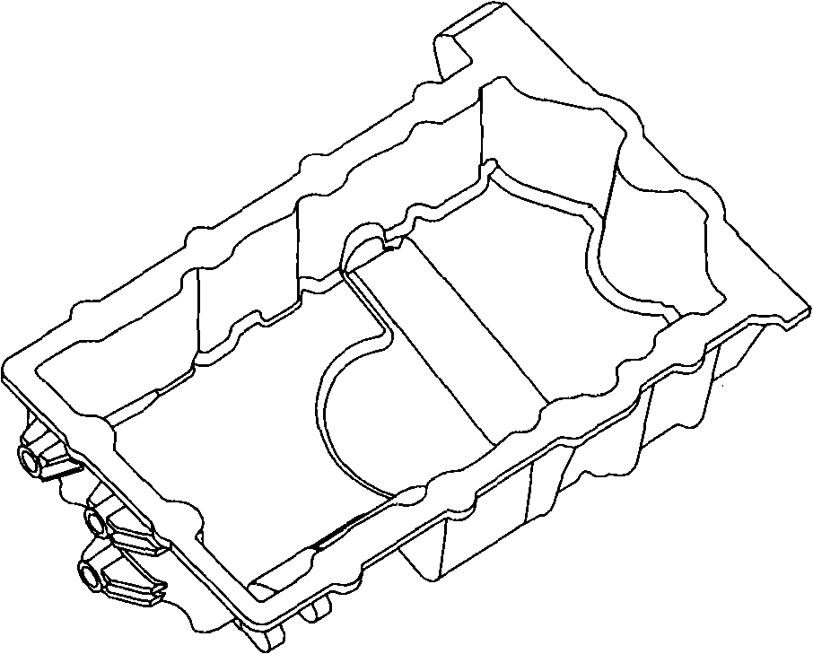
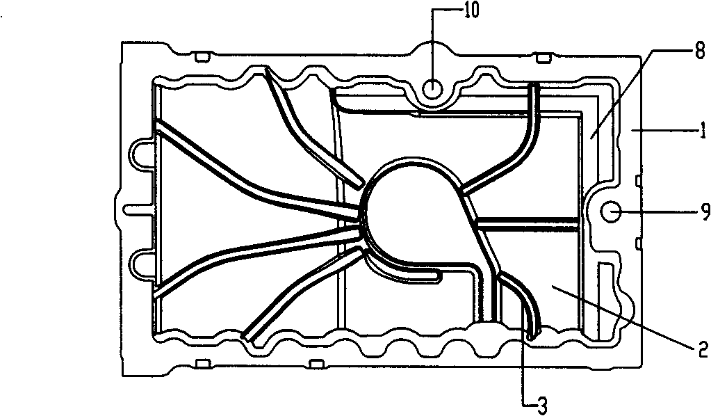
[0019] Example 1, in image 3 , 4 Among them, an engine oil pan, including a large end surface 1 of the oil pan is a horizontal plane, which is directly assembled with the cylinder body by liquid sealant. The sealing effect is good, and the oil is not easy to seep out. Ribs 3 in the inner cavity of the oil pan are arranged in a zigzag direction in the inner cavity 2 of the oil pan, and these ribs form radiation lines, so that sound waves overlap each other and are attenuated. The noise of the volume chamber in vibration is minimized. Bottom ribs 4 staggered horizontally and vertically are arranged at the bottom of the oil pan, which can strengthen the strength of the oil pan and reduce noise. The rear end surface 5 of the oil pan is designed to be a semicircle similar to the profile of the front end surface of the transmission case. Bolt holes 7 for the bolts connected to the transmission are arranged on the oil sump rear face 5 . When this design is adopted, the oil pan ...


PUM


Abstract

The invention provides an oil pan for motors, which comprises a large end face of the oil pan, an internal cavity of the oil pan, a back end face and a bottom of the oil pan, and is characterized in that the internal cavity of the oil pan is provided with internal cavity reinforcement that can reinforce and reduce noises; the bottom of the oil pan is provided with bottom reinforcement; the back end face of the oil pan is provided with back end reinforcement; the back end face of the oil pan is designed into a semi-circle shape, which is similar to the end face shape of the gear-box, and two bolt holes that connect the oil pan and the gear-box are added on the back end face of the oil pan, so the oil pan can be connected with the gear-box directly. The oil pan is set higher than the high-pressure oil channel to favor the arrangement of the whole machine. As the twisted reinforcement that can reinforce and reduce noises are arranged in the internal cavity and the bottom of the oil pan, the noise of oil pan is reduced. As two bolt holes that connect the oil pan and the gear-box are added on the back end face of the oil pan, the oil pan can be connected with the gear-box directly, thereby reducing the guard plates for the motor and the gear-box, reducing the procedure for assembly and reducing the cost. As the high-pressure oil channel is arranged in the internal cavity of the oil pan, the oil channel can convey the high-pressure oil from the oil pump to the motor frame, which is favorable to the arrangement of the whole machine.

Description

technical field [0001] The invention relates to an engine component, more specifically to a structural design of an automobile engine oil pan. Background technique [0002] The engine oil pan is a formed steel oil pan that protects the lower part of the engine and is also the engine's oil reservoir. In the past, there were mainly two types of oil pans: [0003] The first is stamping the oil pan, which uses a thin steel plate to punch out the oil pan. The oil pan has a simple structure and is easily deformed during the running of the vehicle, resulting in oil leakage due to poor sealing between the oil pan and the cylinder body. At the same time, the stamped oil pan is a thin plate. Under high-frequency vibration, it makes a lot of noise and the oil is easy to vaporize. When assembling the engine and gearbox, an assembly guard needs to be added. [0004] The second type is the oil pan made of aluminum-magnesium alloy material. The oil pan only has processing ribs on the b...

Claims


Application Information

Patent Timeline
Patent Type & Authority Applications(China)
IPC IPC(8): F01M11/00
Inventor 罗春宋小平高建鹏王成
Owner CHERY AUTOMOBILE CO LTD
Why Eureka
Try Eureka