Multiple peak narrowband reflection filter possessing broad low reflecting bypass belt

A low-reflection and optical filter technology, applied in optics, optical components, instruments, etc., can solve the problems of limited application range, narrow low-reflection bypass band, etc., to achieve precise control of reflection peak width and position, broaden low-reflection bypass The effect of the passband

Inactive Publication Date: 2008-09-17
TONGJI UNIV
View PDF0 Cites 13 Cited by
  • Summary
  • Abstract
  • Description
  • Claims
  • Application Information

AI Technical Summary

Problems solved by technology

In 2007, Sun et al. proposed and prepared a dielectric-metal filter for the visible light band with a simpler structure, but the low-reflection bypass band of this structure filter is narrow, only 120nm, thus limiting this The scope of application of this structure filter, and the above studies are all carried out for single-peak narrow-band reflection

Method used


Image

  • Multiple peak narrowband reflection filter possessing broad low reflecting bypass belt
  • Multiple peak narrowband reflection filter possessing broad low reflecting bypass belt
  • Multiple peak narrowband reflection filter possessing broad low reflecting bypass belt

Examples


Embodiment Construction

[0048] In the following, the present invention will be specifically described by taking the relationship between spectral characteristics and structural parameters in a multi-peak narrow-band reflective filter with a wide low-reflection bypass band as an example in conjunction with the accompanying drawings.

[0049] figure 1 It is the film system structure Sub|(HL) of the present invention m1 H(α 1 LHLH)(α 2 LHLH)...(α q LHLH)L(HL) m2 Schematic diagram of βMP|Air, the metal layer in the embodiment is Cr.

[0050] 1. Control of index q on the number of reflection peaks

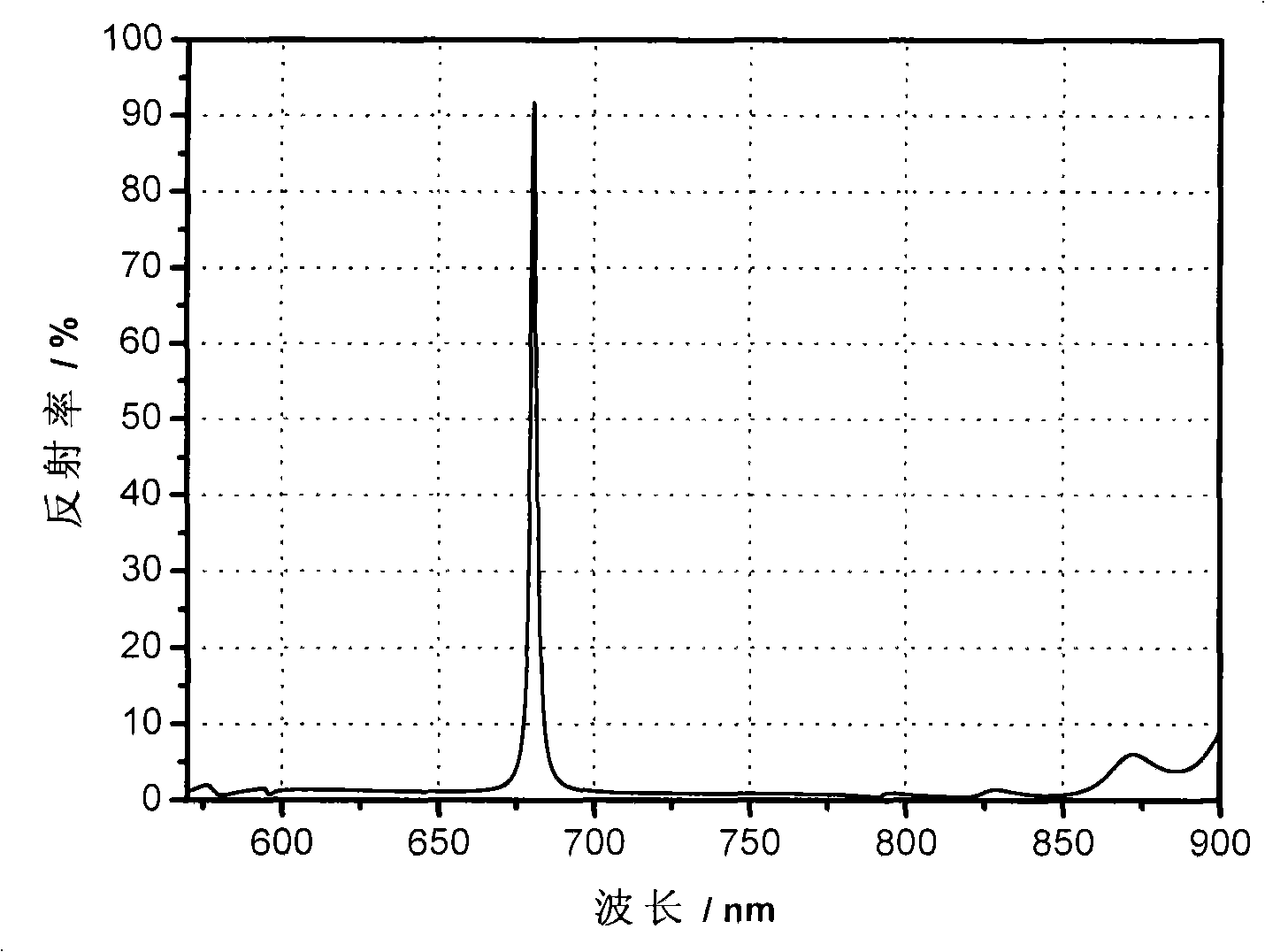
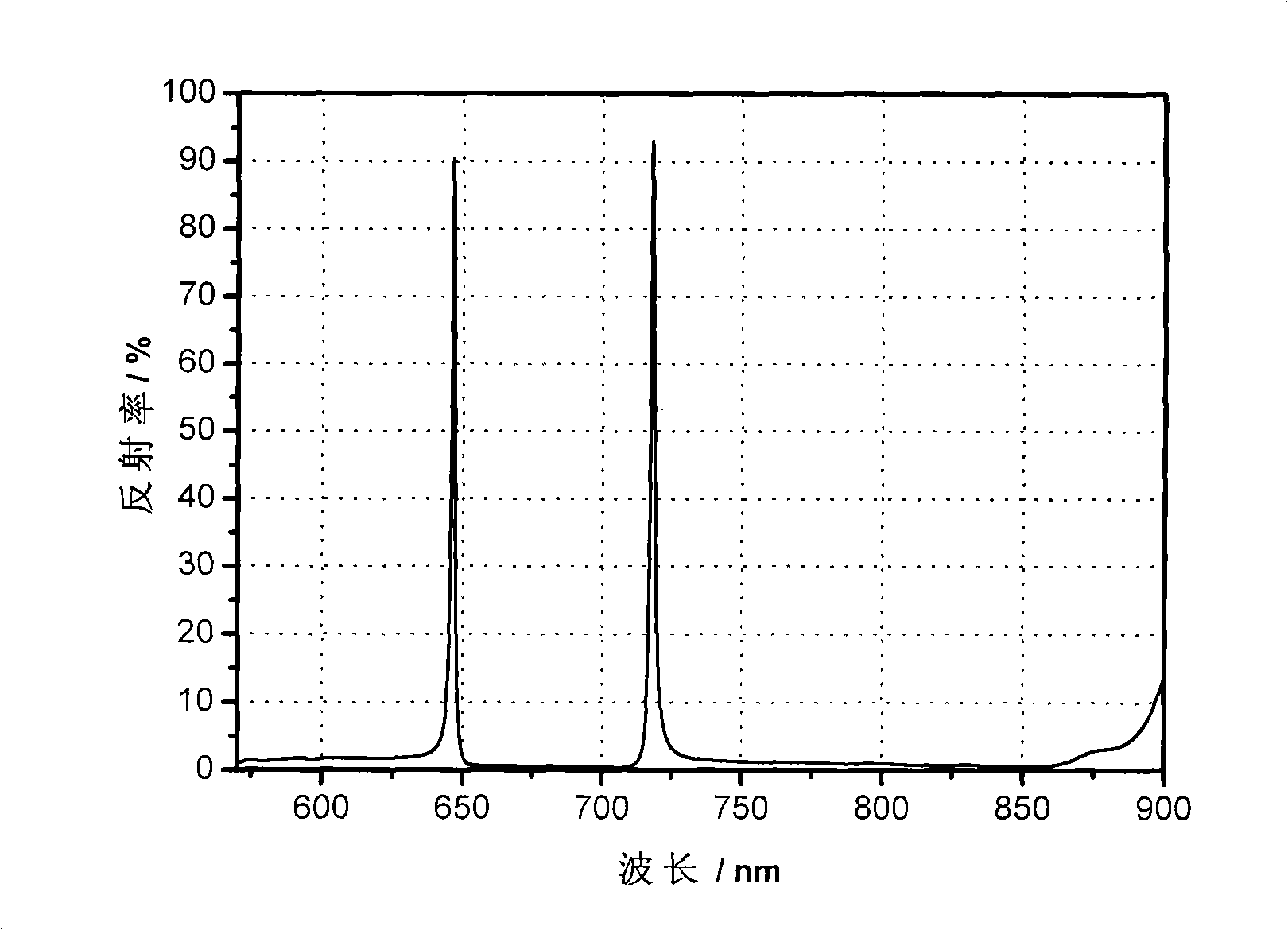
[0051] Figure 2(A)~Figure 2(B) The number of different spacer layers is shown, that is, the relationship between the number of (αLHLH) repeating units q and the number of narrow-band reflection peaks in the designed film system (the designed center wavelength is 700nm), α=2, it is shown in the figure that with the spacer layer With the increase of , the number of narrow-band reflection peaks also incre...


PUM


Abstract

The invention provides a singlet narrowband reflection filter with a wide low reflection bypass band, wherein the membrane structure is a medium-metal composite membrane based on the asymmetric Fabry-Perot structure, namely Sub|(HL)m1H(alpha 1LHLH)( alpha 2LHLH)...(alpha qLHLH)L(HL)m2 beta MP|Air, wherein the Sub is optical thin film substrate; Air is air; H, L respectively is high, low index material of 1/4 wavelength optical thickness; alpha 1, alpha 2...alpha q is the thickness coefficient of the L space layer and q is the number of the (alpha LHLH) repeating units; M is metal layer; beta is thickness of the metal layer; P is the admittance matching layer; m1, m2 is number of the repeating units. The membrane structure is the medium-metal composite membrane based on the asymmetric Fabry-Perot structure with remarkable difference compared with the existing full medium filter, sub-wavelength grating filter. The number of the reflection peak can be adjusted and controlled and the low reflection bypass band can be greatly expanded. The half width and position of the reflection peak can be adjustable, applied to the optical instrument, astronomy, remote observation and optical communication or the like.

Description

technical field [0001] The invention is an optical filter device, specifically relates to a multi-peak narrow-band reflective filter with a wide low-reflection bypass band and a preparation method thereof, and has great potential in optical instruments, astronomy, remote sensing, and optical communications. Application prospects. Background technique [0002] Existing reflective filters generally have the following two types: [0003] 1. Optical films based on all media [0004] A typical reflective filter is a periodic multilayer film structure composed of high and low refractive index materials. There are multiple reflection bands in this structure, namely the main reflection band and the higher order reflection band. The half-width is determined by the relative size of the high and low refractive index of the film layer. For commonly used optical film materials, the bandwidth of the main reflection band is about 30% of the central wavelength of the reflection band, so ...

Claims


Application Information

Patent Timeline
Patent Type & Authority Applications(China)
IPC IPC(8): G02B5/26
Inventor 吴永刚彭东功焦宏飞王振华陈乃波吕刚
Owner TONGJI UNIV
Why Eureka
Try Eureka