
LCD alignment method

A liquid crystal alignment and liquid crystal layer technology, applied in optics, optomechanical equipment, instruments, etc., can solve problems such as high residual amount of monomer materials and poor performance of liquid crystal display panels, so as to improve reliability, avoid damage, and reduce residual volume effect

Active Publication Date: 2008-09-17
AU OPTRONICS CORP
View PDF0 Cites 24 Cited by
  • Summary
  • Abstract
  • Description
  • Claims
  • Application Information

AI Technical Summary

Problems solved by technology

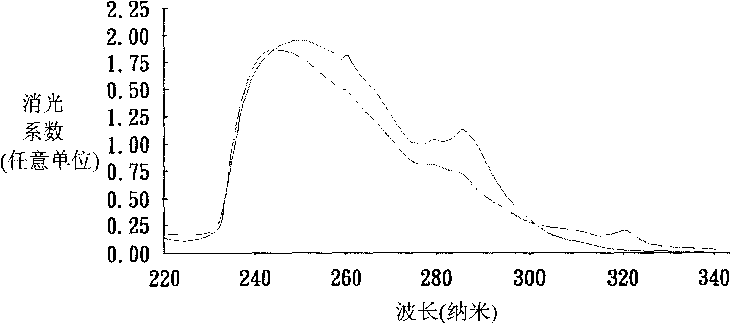
Depend on figure 1 It can be seen that the absorption wavelength of the monomer material is between 220 nanometers (nm) and 340 nanometers, but the above two exposures use ultraviolet light with a main wavelength of about 365 nm, so even if two exposures are performed, the monomer Residual amount of material is still too high
In this way, the performance of the LCD panel in the image sticking test (image sticking test) will be poor

Method used


Image

  • LCD alignment method
  • LCD alignment method
  • LCD alignment method

Examples


Embodiment Construction

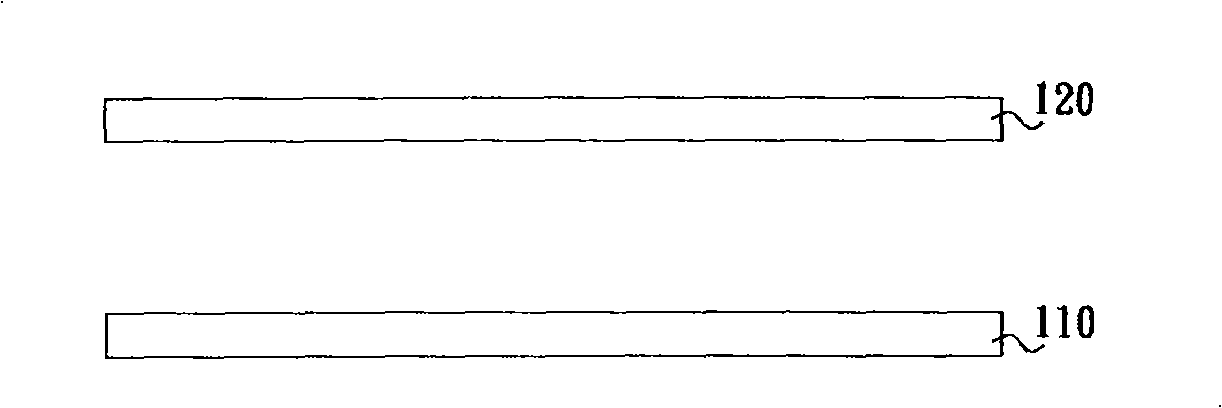
[0026] Figure 2A to Figure 2E It is a flowchart of a liquid crystal alignment method according to an embodiment of the present invention. Please refer to Figure 2A , the liquid crystal alignment method of this embodiment includes the following steps. Firstly, a first substrate 110 and a second substrate 120 are provided. The first substrate 110 is, for example, an active device array substrate, and the second substrate 120 is, for example, a pair of facing substrates.

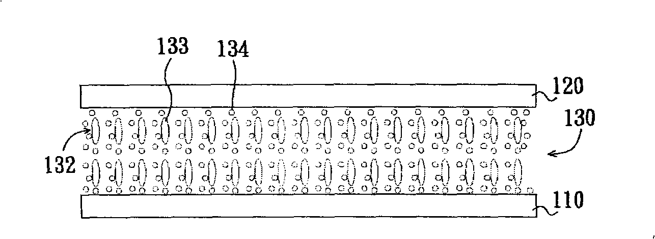
[0027] Next, if Figure 2B As shown, a liquid crystal layer 130 is provided between the first substrate 110 and the second substrate 120, wherein the liquid crystal layer 130 includes a liquid crystal composition 132, a monomer material 134 and a polymerization initiator (not shown). In addition, the liquid crystal composition 132 includes a plurality of liquid crystal molecules 133 .

[0028] Next, apply an electric field to align the liquid crystal molecules 133 in the liquid crystal composition 132 al...


PUM

PropertyMeasurementUnit
Wavelengthaaaaaaaaaa

Abstract

The invention discloses a liquid crystal alignment method includes the following steps: providing a first substrate and a second substrate; providing a liquid crystal layer between the first substrate and the second substrate, wherein the liquid crystal layer includes a liquid crystal composition, a monomer material and a polymerization initiation agent; executing a first exposal proceeding , in order to allow parts of the monomer material to polymerize to form two polymer steadily alignment layers, respectively a first contact face located between the liquid crystal layer and the first substrate, and a second contact face between the liquid crystal layer and the second substrate, in order to allow a plurality of liquid crystal molecules in the liquid crystal composition to align along a pre-inclination angle; and executing a second exposal proceeding , in order to allow the surplus monomer material to polymerize, wherein the second exposal proceeding uses light with the principal wavelength between 290 nanometer to 340 nanometer to irradiate the surplus monomer material. The liquid crystal alignment method can boost the reliability of the liquid crystal display board.

Description

technical field [0001] The invention relates to a manufacturing method of a liquid crystal display panel, in particular to a liquid crystal alignment method. Background technique [0002] With the advancement of flat panel display technology and the advantages of light weight, small size and power saving of flat panel displays, flat panel displays have become more and more popular. Common flat panel displays include liquid crystal display (liquid crystal display, LCD), plasma display panel (plasma display panel, PDP), organic light emitting diode display (organic light emitting diode display, OLED display) and electrophoretic display (electrophoretic display, EPD), among which The penetration rate of liquid crystal display is the highest. [0003] The liquid crystal display includes a liquid crystal display panel (LCD panel) and a backlight module (backlight module), wherein the backlight module is used to provide a display light source to the liquid crystal display panel. ...

Claims


Application Information

Patent Timeline
IPC IPC(8): G02F1/1337G03F7/00G02B1/02
Inventor 黄晟玮陈昭远白家瑄谢忠憬郑德胜杉浦规生
Owner AU OPTRONICS CORP
Learn More