A micro belt aperture shaping wave bundle antenna with serial ladder impedance line feedback

A technology of series feeding and step impedance, which is applied to slot antennas, antennas, antenna arrays, etc., can solve the problems of high processing and manufacturing costs, long feed lines, and large feed line losses, and achieve good impedance matching characteristics, low manufacturing costs, and structural simple effect

Inactive Publication Date: 2008-09-17
SOUTH CHINA UNIV OF TECH
View PDF0 Cites 11 Cited by
  • Summary
  • Abstract
  • Description
  • Claims
  • Application Information

AI Technical Summary

Problems solved by technology

[0002] The traditional beamforming implementation is mostly used to control the amplitude and phase of the antenna unit by using a parallel feed network. This method can conveniently control the array, but it requires additional design of the feed network, which increases the complexity of the system on the one hand. On the other hand, the parallel feeder network generally has a long feeder, so the feeder loss is relatively large
In the past ten years, the series-fed shaped beam antenna has also been extensively studied, that is, a feeder is used to feed all the array radiating elements in series. Although the feed power distribution network is saved, each The control of the feed amplitude and phase on the unit becomes relatively complicated, and it must be realized by changing the structure of the radiation unit and then changing its impedance characteristics, which greatly increases the technical difficulty and cost of antenna design
The more common series-fed shaped beam antenna, the so-called "Xilianchuan" antenna, is composed of the inner and outer conductors of the coaxial line alternately connected. This structure can achieve higher gain and omnidirectional radiation characteristics, but , its structure is complex, and its processing cost is relatively high. At the same time, it is difficult to precisely control its pattern during the design process. Therefore, its beam forming characteristics are often not very good, and it can only achieve beam zero filling within a certain angle range.

Method used


Image

  • A micro belt aperture shaping wave bundle antenna with serial ladder impedance line feedback
  • A micro belt aperture shaping wave bundle antenna with serial ladder impedance line feedback

Examples


Embodiment Construction

[0017] The present invention will be further described in detail below in conjunction with the embodiments and accompanying drawings, but the protection scope of the present invention is not limited to the scope involved in the embodiments.

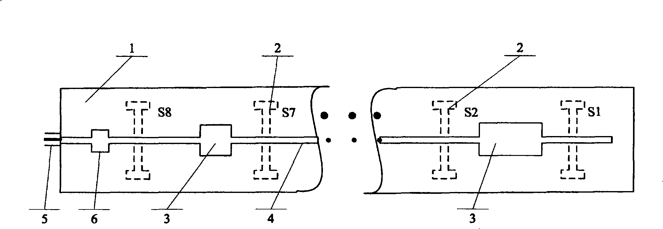
[0018] The antenna structure provided by the present invention is as figure 1 As shown, the antenna is fabricated on a double-sided metal-clad microstrip dielectric board 1 in the form of a printed circuit board. One side of the microstrip dielectric board 1 is a metal-clad ground plane, and more than 3 slot radiation units are etched. 2. The shape of the slot radiation unit 2 can be H-shaped or straight. On the other side of the microstrip plate dielectric plate 1 is a microstrip line formed by series connection of two microstrip lines 3 and 4 with different characteristic impedances. Between every two slot radiation units 2, there is one and only one section of microstrip line 3, and the other microstrip lines are all microstrip lines ...


PUM


Abstract

The present invention provides a microstrip slot shaped beam antenna of series fed by step-impedance line, composed of a microstrip dielectric slab which two sides are covered by metal, one side of the microstrip dielectric slab serving as a grounding plate is etched more than three identical gap radiation units which are arranged by same distance, the other side is provided with a microstrip line composed of the alternatively serial connection of two microstrip lines having different characteristic impedances, the impedance ratio of the two different characteristic impedances microstrip lines is more than 1.6; the relationship of the two microstrip lines is that: the other microstrip line is serially connected on one microstrip line between any two gap radiation units; the microstrip line protrudes from the first gap radiation unit to realize the short circuit feed of the first gap radiation unit. The antenna has a simple structure, light weight, easier design, lower cost, fit for the signal cover of the narrow and long region such as tunnel, expressway, long buildings.

Description

technical field [0001] The invention relates to wireless communication equipment, in particular to a microwave antenna, in particular to a microstrip slot-shaped beam antenna fed in series with stepped impedance lines. Background technique [0002] The traditional beamforming implementation is mostly used to control the amplitude and phase of the antenna unit by using a parallel feed network. This method can conveniently control the array, but it requires additional design of the feed network, which increases the complexity of the system on the one hand. On the other hand, the parallel feeder network generally has a long feeder, so the feeder loss is relatively large. In the past ten years, the series-fed shaped beam antenna has also been extensively studied, that is, a feeder is used to feed all the array radiating elements in series. Although the feed power distribution network is saved, each The control of the feed amplitude and phase on the unit becomes relatively compl...

Claims


Application Information

Patent Timeline
Patent Type & Authority Applications(China)
IPC IPC(8): H01Q13/10H01Q13/08H01Q21/00
Inventor 褚庆昕马汉清
Owner SOUTH CHINA UNIV OF TECH
Why Eureka
Try Eureka