
Two-line optical sensing network and its method based on spectrum division multiplexing method

A technology of optical fiber sensing and optical fiber sensor, which is applied in the network field, can solve problems such as low reliability, small system flexibility, and reduced measurement accuracy, and achieve the effect of reducing requirements and enhancing system multiplexing capabilities

Inactive Publication Date: 2008-09-17
SHANDONG UNIV
View PDF0 Cites 8 Cited by
  • Summary
  • Abstract
  • Description
  • Claims
  • Application Information

AI Technical Summary

Problems solved by technology

[0005] (1) In the one-line optical fiber sensor network, the energy signal (the optical signal emitted by the broadband light source) and the measurement signal (the optical signal returned by the optical fiber sensor) are transmitted bidirectionally along the same optical fiber, which cannot be amplified, so it is not conducive to Long-distance measurement is not conducive to improving the signal-to-noise ratio of the system;
[0006] (2) In the one-line optical fiber sensor network, the fiber optic sensors are connected in series and have the same structure type (that is, the same reflective fiber sensor or the same transmissive fiber sensor), so the system has little flexibility and low reliability;
[0007] (3) In the one-line optical fiber sensor network, since the wavelength ranges of different sensors cannot overlap, when the system capacity (that is, the number of measurement points) increases, the measurement range of the measurement points will decrease accordingly, and the measurement accuracy will also decrease accordingly, which cannot meet the needs of engineering applications. The requirements of "increased measurement accuracy when the range is reduced";
[0008] (4) In the one-line optical fiber sensor network, the system capacity is determined at the time of design, and it is fixed after completion, and it is not easy to expand, so it cannot meet the user's requirements for system expansion in subsequent use

Method used


Image

  • Two-line optical sensing network and its method based on spectrum division multiplexing method
  • Two-line optical sensing network and its method based on spectrum division multiplexing method
  • Two-line optical sensing network and its method based on spectrum division multiplexing method

Examples


Embodiment Construction

[0044] The present invention will be further described below in conjunction with the accompanying drawings and embodiments.

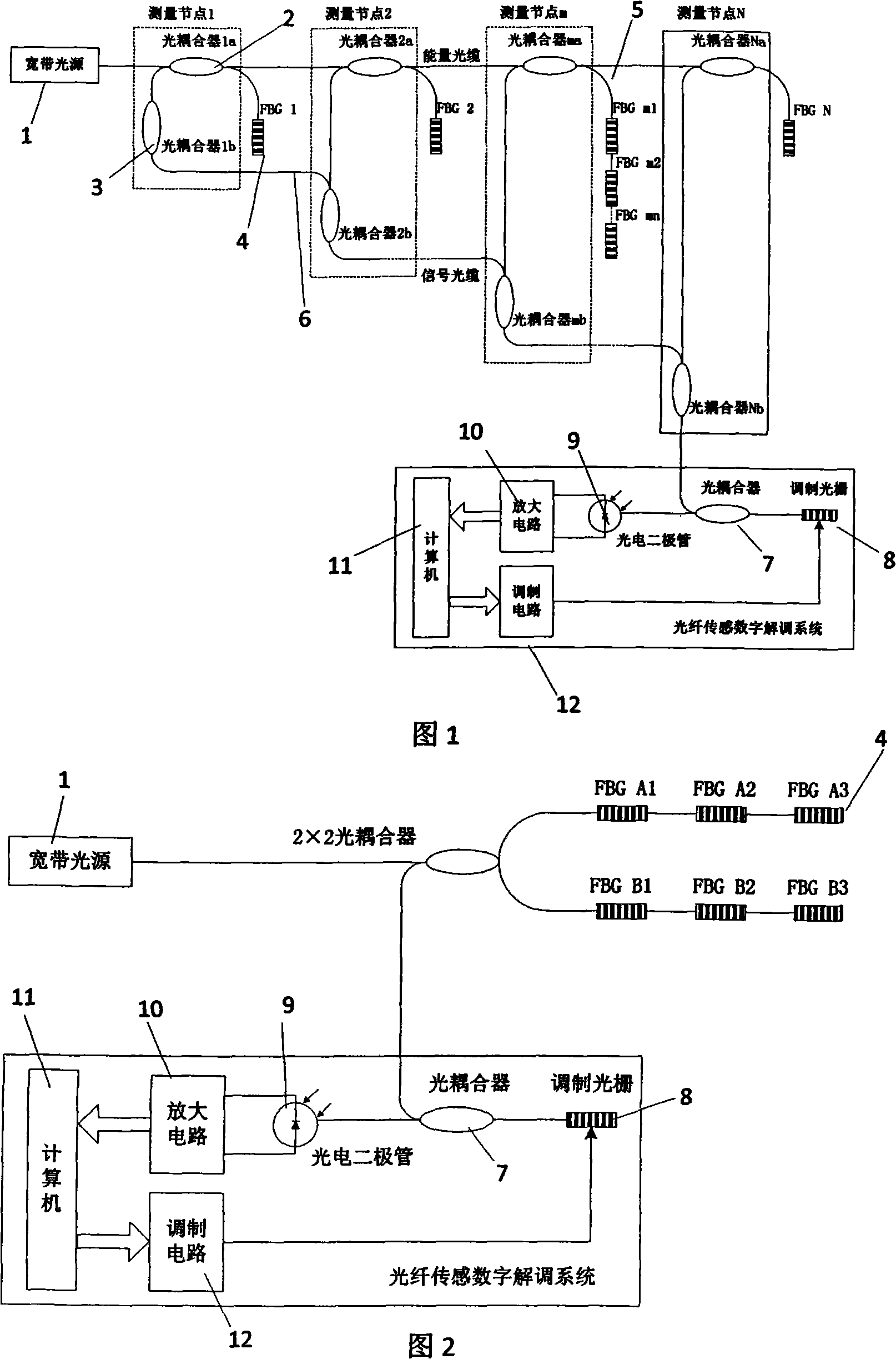
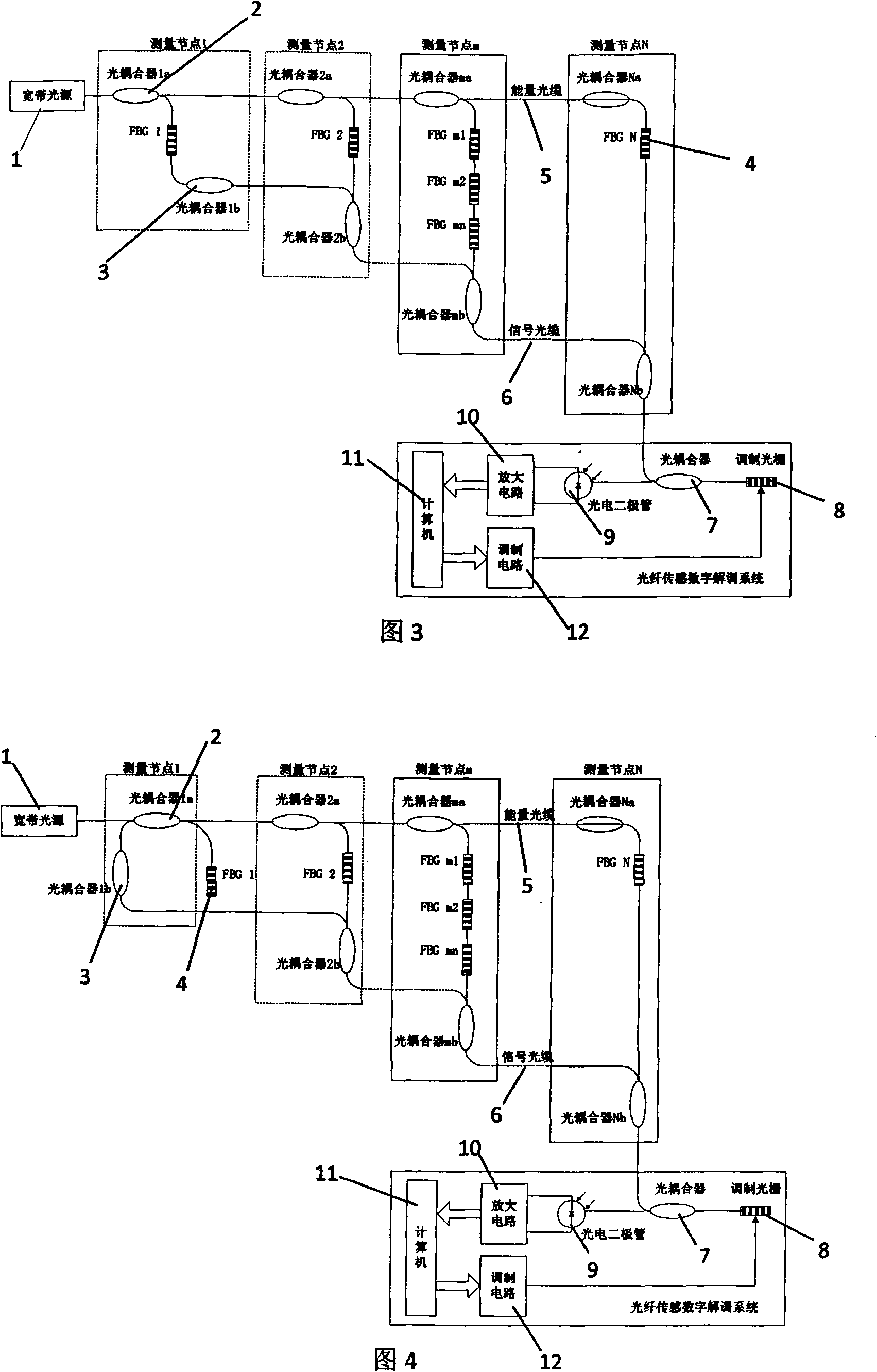
[0045] It can be seen from Figure 1 that the two-wire optical fiber sensor network is mainly composed of two mutually independent optical fibers, among which the optical fiber connected to the output end of the broadband light source 1 is called the energy optical fiber 5, which is used to transmit energy signals and distribute optical energy to each measurement node ; The optical fiber connected to the signal output end of each measurement node is called signal fiber 6, which is used to transmit measurement signals, and the signals output by different measurement nodes are synthesized into one bundle and then sent to the digital demodulation system for processing. A plurality of measurement nodes are distributed between the energy fiber 5 and the signal fiber 6, and each measurement node includes two optical couplers: an optical coupler a 2 and an optic...


PUM


Abstract

The present invention discloses a two-wire system optical fiber sensing network basing on the method of frequency division multiplexing and a method thereof. The network is easy to be expanded. The optical spectrum signal which includes the measured physical quantity information is executed with effective amplification. The signal obtained by the receiving end is guaranteed to have high signal-to-noise ratio. The invention has the advantages of facilitated far transmission, easy maintenance, high reliability, and being suitable for the project application. The structure is that the network comprises two optical fibers which are independent from each other. One optical fiber in the two optical fibers is an energy optical fiber which is connected to the output end of the light source of the wideband, and is provided with a plurality of optical couplers a whereon. Each optical coupler a is connected with at least one sensor to realize the distributed measurement. The other optical fiber is a signal optical fiber which is also provided with a plurality of optical coupler b whereon. Each optical coupler b of the signal optical fiber is connected with the signal output end of each corresponding optical coupler a of the energy optical fiber to form a measuring node. Each measuring node respectively combines the output signal of the respectively corresponding optical coupler a to a beam through the optical coupler b which is arranged in the measuring node and transmits the beam to a digital demodulation system.

Description

technical field [0001] The invention relates to a network, in particular to a two-wire optical fiber sensing network based on a spectrum division multiplexing method and a method thereof. Background technique [0002] As a new type of sensor device, the biggest feature of the fiber grating sensor is its strong multiplexing ability and low transmission loss. It is easy to form an optical fiber sensor network through various multiplexing technologies. There are broad application prospects in many fields, and they have been greatly developed in recent years. [0003] When forming an optical fiber sensor network, some multiplexing schemes in optical communication technology are usually used, such as wavelength division multiplexing scheme, time division multiplexing scheme, space division multiplexing scheme, frequency division multiplexing scheme and hybrid multiplexing scheme, etc. . Among them, wavelength division multiplexing technology has become the most basic and main m...

Claims


Application Information

Patent Timeline
Patent Type & Authority Applications(China)
IPC IPC(8): H04B10/12H04B10/08H04B10/20H04B10/25
Inventor 李东升贾磊隋青美曹玉强
Owner SHANDONG UNIV
Learn More