
Process and apparatus for the separation of air by cryogenic distillation

A low-temperature distillation and air separation technology, applied in the field of high pressure oxygen and/or nitrogen production, can solve the problems of high compressor discharge pressure, increased cost, insufficient power usage, etc.

Inactive Publication Date: 2008-09-17
LAIR LIQUIDE SA POUR LETUDE & LEXPLOITATION DES PROCEDES GEORGES CLAUDE
View PDF5 Cites 2 Cited by
  • Summary
  • Abstract
  • Description
  • Claims
  • Application Information

AI Technical Summary

Problems solved by technology

However, this results in insufficient power usage and high compressor discharge pressure, thereby increasing its cost

Method used


Image

  • Process and apparatus for the separation of air by cryogenic distillation
  • Process and apparatus for the separation of air by cryogenic distillation
  • Process and apparatus for the separation of air by cryogenic distillation

Examples


Embodiment Construction

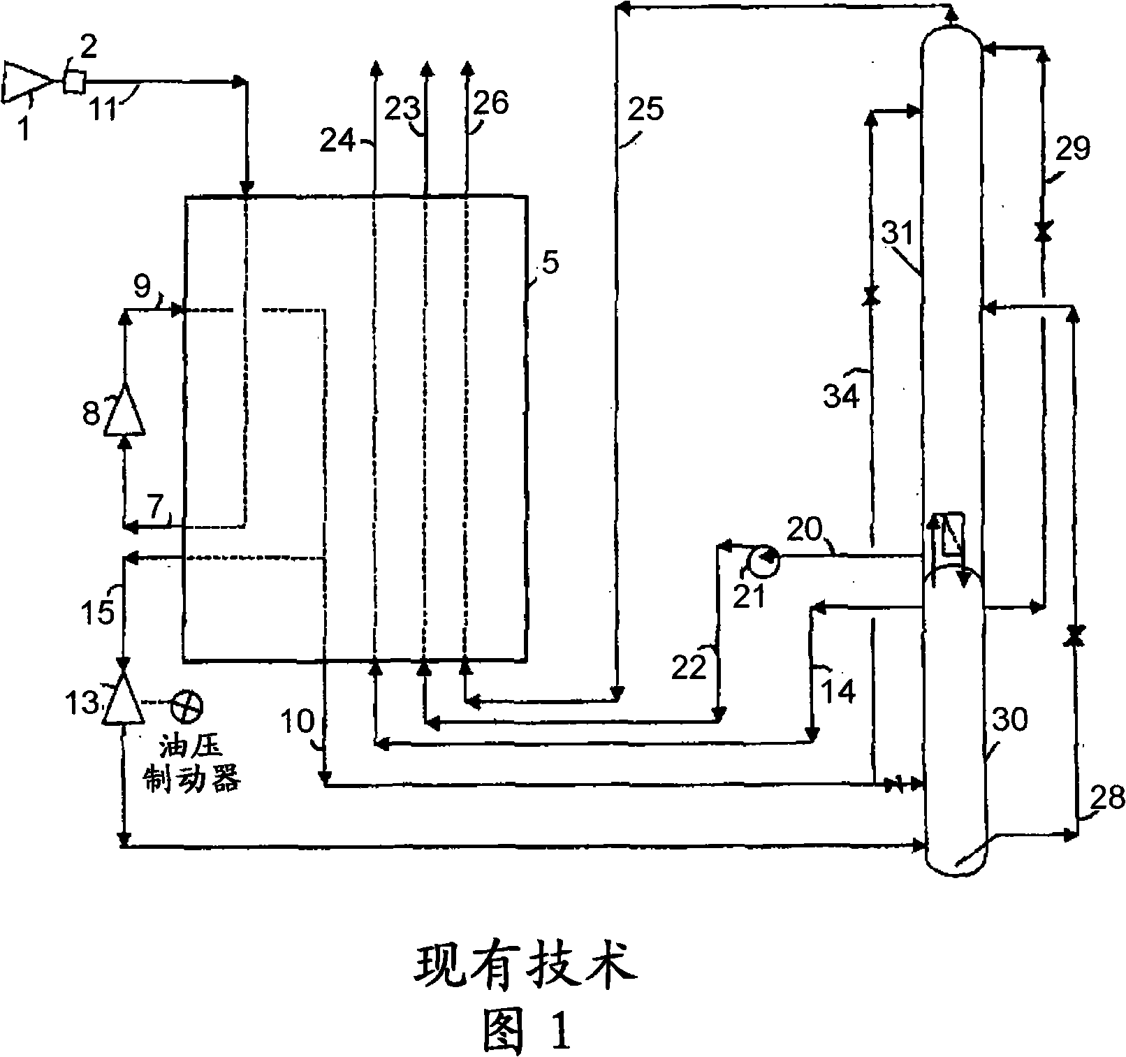
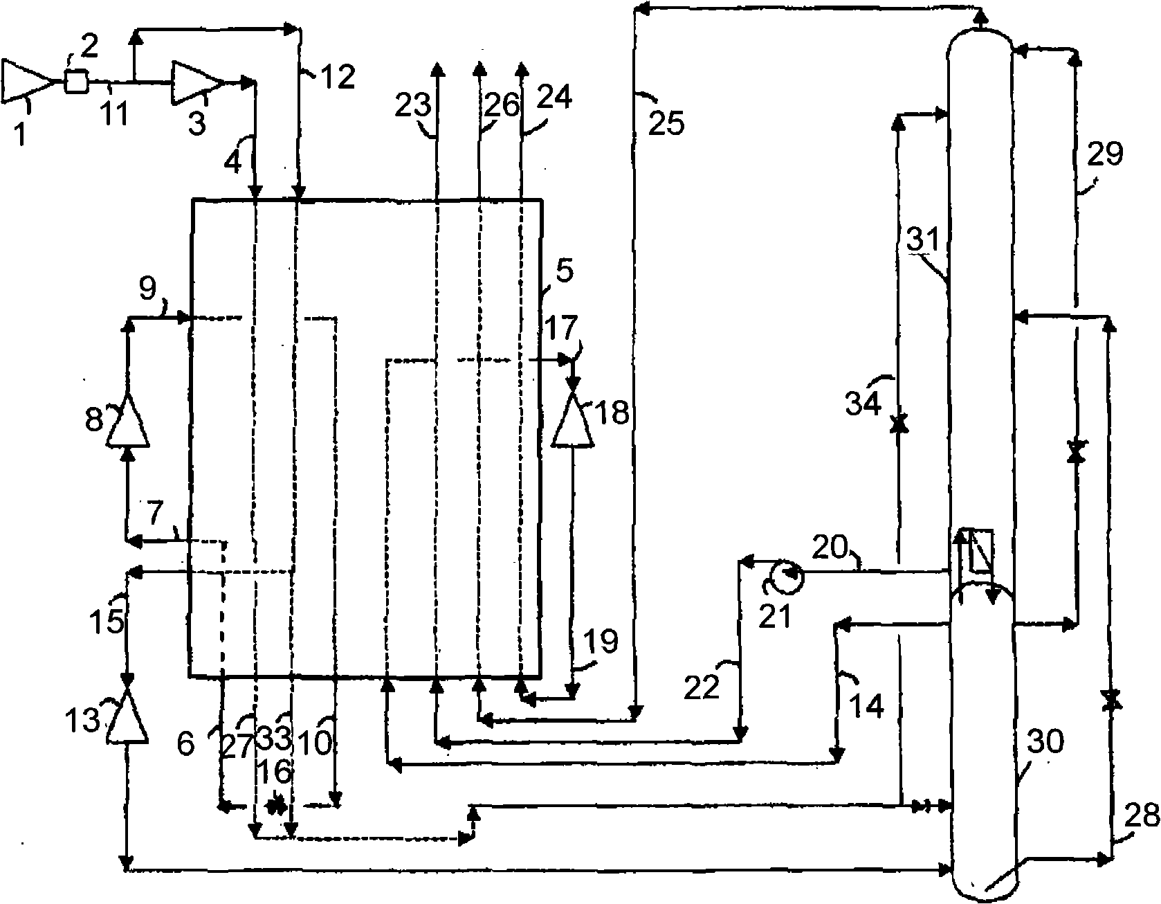
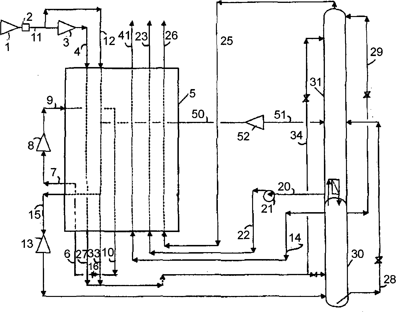
[0046] exist figure 2 In an embodiment of the present invention, the atmosphere is compressed by an air compressor 1 and purified in a purification unit 2 to produce an air stream (stream 11 ) free of impurities such as moisture and carbon dioxide that can freeze in cryogenic equipment. A first part of the air is compressed in a boosterbrake compressor 3 to further boost its pressure. This pressurized first portion (stream 4) is then cooled in main heat exchanger 5 to condense to form a liquefied air stream (stream 27) which is expanded in a valve and fed to at least one distillation column. Depending on the pressure used, the air can be liquefied in the main heat exchanger or downstream of the main heat exchanger. An auxiliary fluid mixture 6 of krypton (90%) and oxygen (10%) is introduced into the heat exchanger 5 where it is vaporized and warmed up slightly after vaporization to generate a cold auxiliary gaseous stream at an intermediate temperature T1 . At least a part ...


PUM


Abstract

A process for separating air by cryogenic distillation in a column system comprising a high pressure column and a low pressure column comprises compressing all the feed air in a first compressor (1) to a first outlet pressure, sending a first part of the air at the first outlet pressure to a second compressor (3) and compressing the air to a second outlet pressure, cooling at least part of the air at the second outlet pressure in a heat exchanger (5) liquefying at least part of the air at the second outlet pressure and sending the liquefied air to at least one column of the column system wherein at least 50% of the liquefied air sent to the column system has been compressed in the second compressor, cooling a second part of the air (12) at the first outlet pressure in the heat exchanger and expanding at least part of the second part of the air in an expander (13) from the first outlet pressure to the pressure of a column (30, 31) of column system and sending the expanded air to that column, at least partially vaporizing an auxiliary fluid (6) , eventually further warming said auxiliary fluid in the heat exchanger, sending at least part of this auxiliary fluid to a third compressor (8) to a third outlet pressure, introducing at least part (9) of said auxiliary fluid at said third outlet pressure in the heat exchanger, cooling said auxiliary fluid and at least partially liquefying said auxiliary fluid, removing said auxiliary stream (10) from the heat exchanger and expanding (16) it to a fourth pressure level before reintroducing it in the heat exchanger where it will be partially vaporized as above- mentioned, removing liquid (20) from a column (31) of the column system and vaporizing the liquid by heat exchange in the heat exchanger.

Description

technical field [0001] The present invention relates to a method and an apparatus for separating air by cryogenic distillation. In particular the invention relates to methods and apparatus for producing high pressure oxygen and / or nitrogen. Background technique [0002] Gaseous oxygen produced by air separation plants is usually at high pressure of about 20 to 50 bar. The basic distillation scheme is usually a two-column process producing oxygen at the bottom of a low pressure column operating at a pressure of 1.4 to 4 bar. Oxygen must be compressed to a higher pressure by an oxygen compressor or by liquid pumping methods. Due to the safety concerns associated with oxygen compressors, most oxygen generating equipment today is based on the liquid pumping method. To vaporize high pressure liquid oxygen, an additional motor driven booster compressor is required to boost a portion of the feed air or nitrogen to a higher pressure in the range of 40-80 bar. In essence, the oxy...

Claims


Application Information

Patent Timeline
IPC IPC(8): F25J3/04
CPCF25J3/04393F25J3/04381F25J2230/20F25J3/04412F25J2270/902F25J3/04145F25J3/04024F25J3/04139F25J3/04296F25J2230/08F25J2290/12F25J2270/12F25J3/04278F25J3/04109F25J3/04303F25J2270/66F25J3/0409F25J3/04309
Inventor J-P·特拉尼耶
Owner LAIR LIQUIDE SA POUR LETUDE & LEXPLOITATION DES PROCEDES GEORGES CLAUDE
Learn More