Industrial production sling safety system and security protection method

A technology of safety protection and spreader, applied in the direction of safety device, load hanging element, fluid pressure actuating device, etc., can solve the problems of increasing system failure, gas circuit control failure, lack of concentration, etc., to ensure safety performance, The effect of eliminating misoperation and simple structure

Active Publication Date: 2008-09-24
CHERY AUTOMOBILE CO LTD
View PDF0 Cites 16 Cited by
  • Summary
  • Abstract
  • Description
  • Claims
  • Application Information

AI Technical Summary

Problems solved by technology

However, with the acceleration of the production rhythm, the operator sometimes loses concentration due to fatigue and paralysis, and misoperation occurs from time to time; in addition, due to the long-term use of the equipment, gas circuit control components and tracheal loss will cause gas breakage and gas leakage , resulting in the failure of the gas path contr

Method used


Image

  • Industrial production sling safety system and security protection method

Examples


Embodiment 1

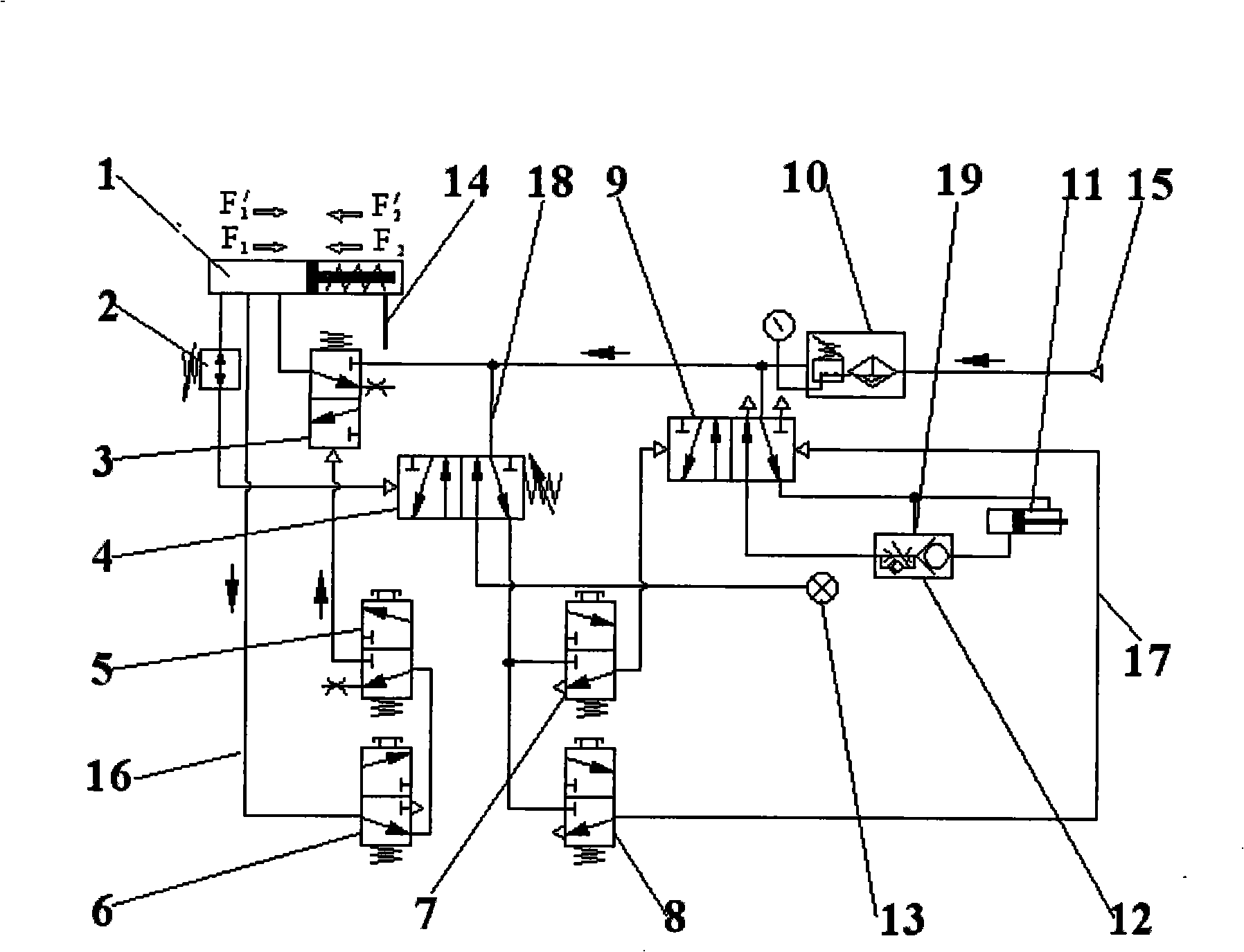
[0042] Embodiment 1. The structure and components of the lifting control air circuit 16 of the spreader:

[0043] In the lifting control air circuit 16 of the spreader described in the above scheme, an up button 5, a down button 6 and an air balancer air intake control valve 3 are set, and the air cavity of the air balancer 1 is controlled by the air intake of the air balancer. When the valve 3 is in the working position, the intake air is from the main air source 15, the air intake control valve 3 of the pneumatic balancer is controlled by the up button 5 to make the air chamber of the pneumatic balancer 1 intake air, and the air balancer 1 is controlled by the down button 6 to make the air flow of the air balancer 1 Cavity throttling exhaust.

[0044] The above-mentioned structure makes the lift of the spreader controlled by the main air source 15 to provide the required power, and the air balancer air intake control valve 3 realizes the on-off of the lift air circuit, so as...

Embodiment 2

[0045] Embodiment 2, the specific structure of the pneumatic balancer intake control valve 3, the up button 5 and the down button 6:

[0046] The pneumatic balancer intake control valve 3 described in Embodiment 1 is a two-position three-way valve whose working position is controlled by pneumatics and the normal position is reset by a spring; Control and normal position are spring-returned two-position three-way valves.

[0047] This embodiment solves the structural forms of the above three pneumatic control elements. Its structure is a two-position three-way valve with spring return, which is simple in structure and good in versatility. In particular, the up button 5 and the down button 6 are actually two pneumatic valves, which are in the form of buttons to directly control the gas circuit, reduce the number of control links, and improve their reliability.

Embodiment 3

[0048] Embodiment 3. The gas path connection relationship of the lifting control gas path 16 of the spreader is as follows:

[0049] The air cavity of the pneumatic balancer 1 described in the above two embodiments, the down button 6, the up button 5, and the working position of the air balancer air intake control valve 3 are sequentially connected through the air circuit;

[0050] When the down button 6 is in the normal position, the air cavity of the pneumatic balancer 1 communicates with the up button 5, and when it is in the working position, the air cavity of the pneumatic balancer 1 communicates with the throttle exhaust port on the down button 6;

[0051] When the up button 5 is in the normal position, the air port connected with the down button 6 is closed, and when it is in the working position, the gas path of the down button 6 is connected with the working position of the air intake control valve 3 of the pneumatic balancer;

[0052] When the pneumatic balancer inta...


PUM


Abstract

The invention discloses an industrial production lifting tool safety protection system, which comprises a pneumatic balancer (1), a clamping cylinder (11) and a main air supply (15), wherein, the pneumatic balancer is used for the elevation and the subsidence of a lifting tool; the clamping cylinder is used for tightly holding a workpiece; the main air supply is used for the drive and the control; the safety protection system is provided with a lifting tool elevation-subsidence control air circuit (16), a workpiece clamping air circuit (17), an elevation-subsidence and clamping interlocking air circuit (18) and an air-break protection air circuit (19), and each of the air circuits is communicated with the main air supply (15) by the same air circuit. The invention also relates to a safety protection method adopted by the industrial production lifting tool safety protection system. By adopting the technical proposal, a production lifting tool used in industrial production especially automobile industrial production realizes mutually correlative multiple safety protection, the safety protection system has the advantages of simple and reasonable structure and convenient and reliable operation, and the safety performance of the system is guaranteed and accidents of incorrect manipulation, air break, air leakage, etc. are stopped to happen.

Description

technical field [0001] The invention belongs to the technical field of process equipment for industrial production, and relates to the process equipment for transferring workpieces in the production process. More specifically, the invention relates to a safety protection system for industrial production slings. The invention also provides the safety protection method adopted by the safety protection system of the industrial production spreader. Background technique [0002] At present, in the welding production line of automobile manufacturing enterprises, spreaders are used to carry out operations such as transferring, subpackaging, and hoisting of workpieces. In order to make the operation of the spreader equipment better meet the production process requirements and production rhythm, most manufacturers generally use the cylinder as the power source to drive the mechanical structure, realize the clamping and loosening of the spreader, and make the workpiece rise or fall. ...

Claims


Application Information

Patent Timeline
IPC IPC(8): B66C15/00B66C13/18F15B13/02
Inventor 曹阳天魏国杰
Owner CHERY AUTOMOBILE CO LTD
Why Eureka
Try Eureka