Gas oil separation structure of internal combustion engine crankcase ventilation system

A technology for crankcase and ventilation system of internal combustion engine, applied in the field of lubrication system, can solve the problems of high oil consumption and low consumption of lubricating oil, and achieve the effect of high oil-gas separation efficiency, reduced consumption of lubricating oil and compact structure

Inactive Publication Date: 2008-09-24
CHONGQING CHANGAN AUTOMOBILE CO LTD
View PDF0 Cites 23 Cited by
  • Summary
  • Abstract
  • Description
  • Claims
  • Application Information

AI Technical Summary

Problems solved by technology

[0004] The purpose of the present invention is to provide a simple and efficient oil-gas separation structure for the crankcase ventilation system of an internal combustion engine, which solves the problem of large oil consumpti

Method used


Image

  • Gas oil separation structure of internal combustion engine crankcase ventilation system
  • Gas oil separation structure of internal combustion engine crankcase ventilation system
  • Gas oil separation structure of internal combustion engine crankcase ventilation system

Examples


Embodiment Construction

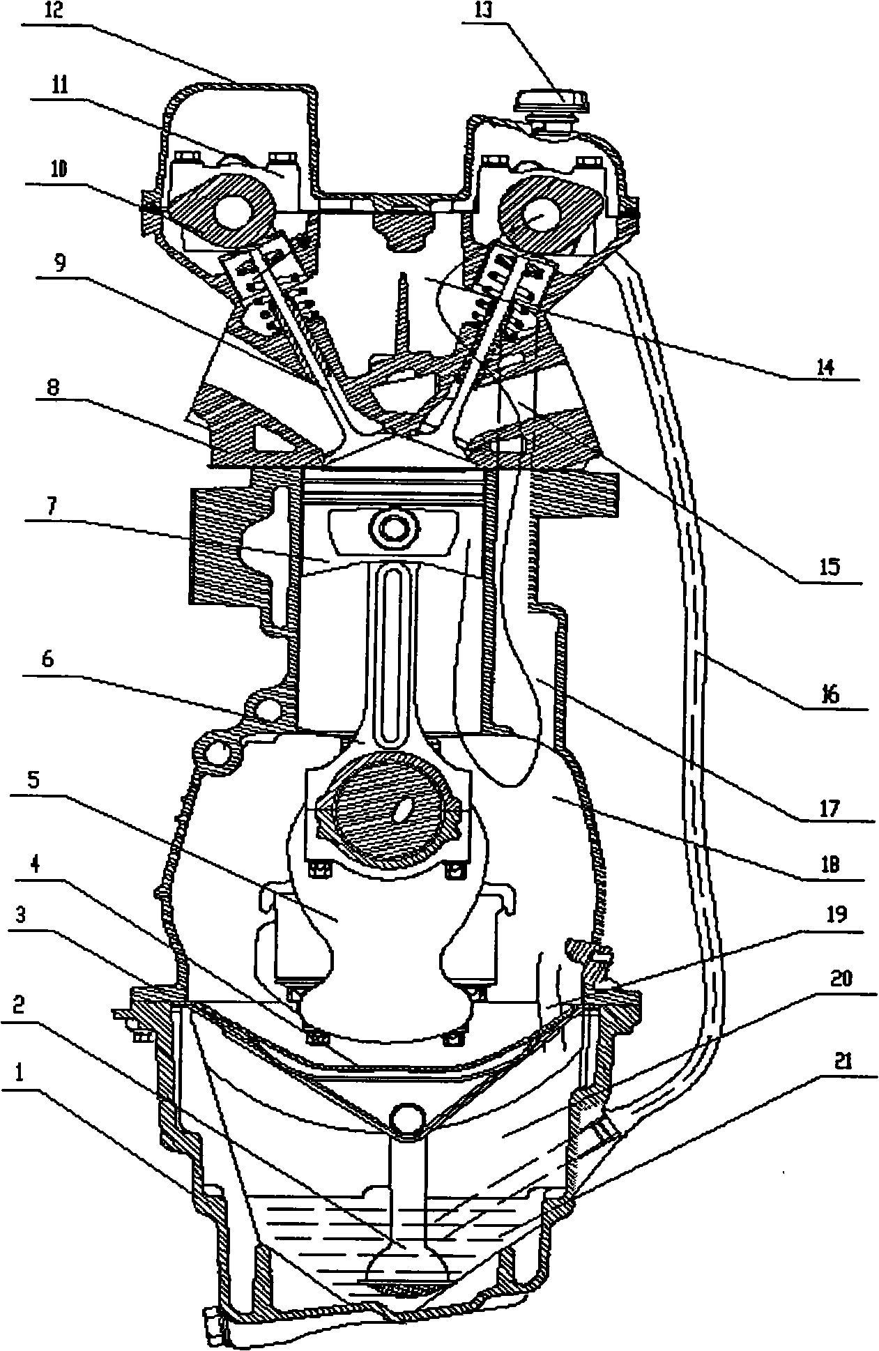
[0013] see figure 1 , the usual internal combustion engine main body structure consists of crankcase 3, crankshaft 5, connecting rod 6, piston 7, camshaft 10, valve train components 9, cylinder head 8 and cylinder head cover 12, oil pan 1, oil filter 2, PCV valve 25 and so on. Wherein, the engine oil pan 1 and the engine oil reflector 4 form the engine oil chamber 20, and there is an oil gas channel 19 passing through the engine oil reflector. Crankcase 18 is formed by crankcase 3, crankshaft 5, connecting rod 6, and piston 7. There is a vent chamber 17 with a small upper opening and a larger lower opening at the crankcase 3 edge. Also there is a ventilation chamber 15 at the cylinder head 8, and at the top of the cylinder head 8, the valve chamber 14 is formed by the valve train element 9, the cylinder head cover 12, and the filler cap 13.

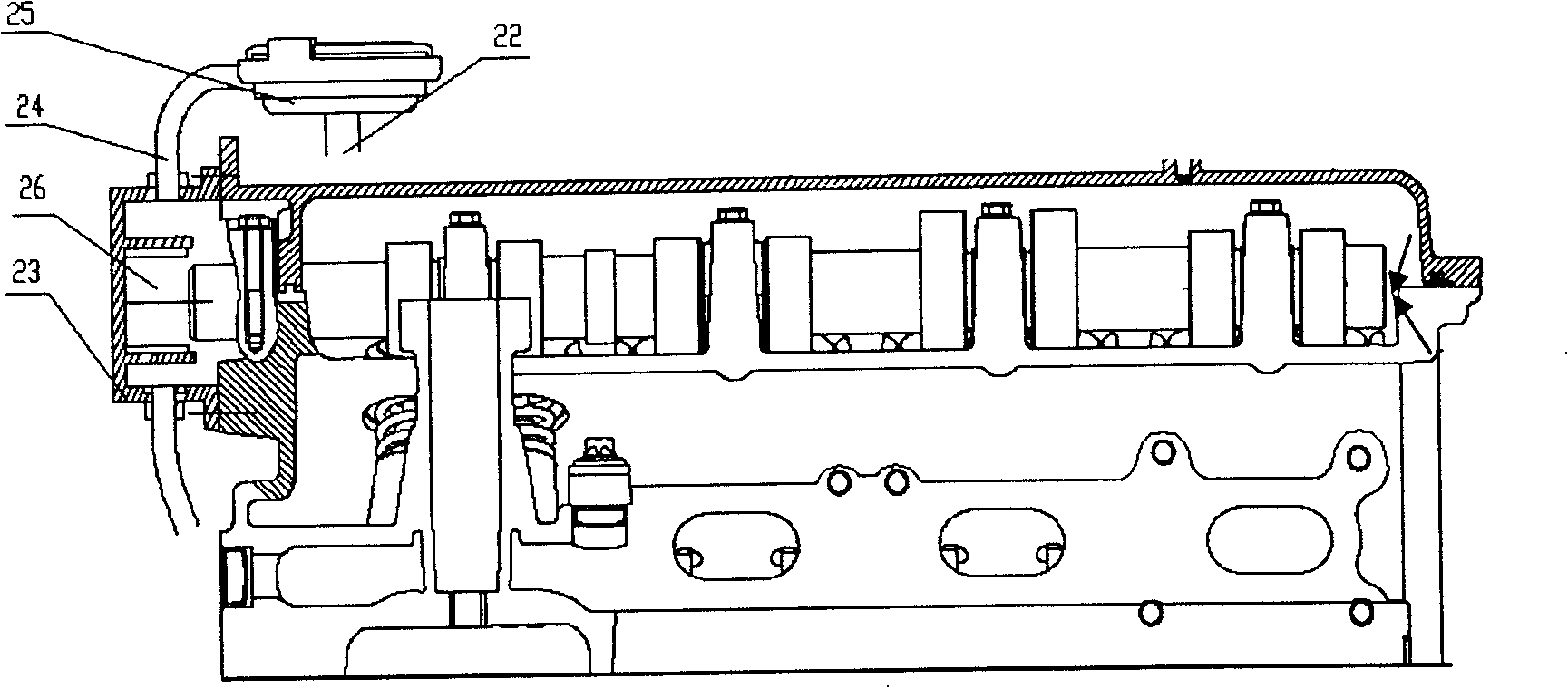
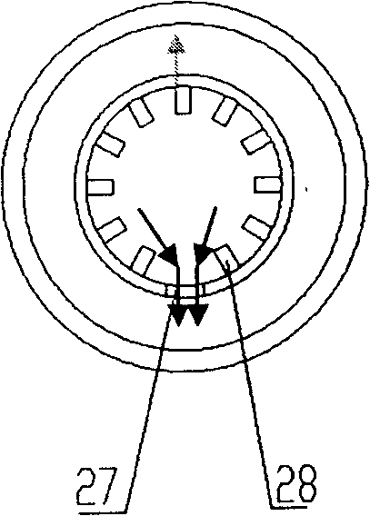
[0014] combine figure 2 and image 3 It can be seen that the crankcase ventilation structure is arranged on the cylinder head cover...


PUM


Abstract

The invention relates to gas-oil dissociation structure of a ventilating system of an internal-combustion engine crankcase, comprising a cylinder head, a camshaft cover and a camshaft. One end of the camshaft extends and outstretches the cylinder head that is covered by an end cap. The end cap and the cylinder head are fixed to form an impact dissociation chamber with the cylinder head and the camshaft. The bottom of the end cap is provided with an impact slot. The upper and the lower sides of the end cap are provided with a gas vent and an oil-returning opening. The gas vent upwards goes through an air channel and enters a PCV valve. The oil-returning opening downwards goes through an oil-returning pipe and is connected with the engine oil chamber of the crankcase. The structure of the camshaft is hollow with a rotary dissociation chamber formed in middle. The end of the rotary dissociation chamber facing one end of the end cap is an air outlet and the other end of the rotary dissociation chamber is an air inlet. A plurality of pores are distributed among the middle part of the camshaft that are communicated with the rotary dissociation chamber and a valve chamber. The gas-oil dissociation structure leads the inter-combustion engine to higher efficiency of gas-oil dissociation. On the premise that the pressure of the crankcase is ensured to be in line with state rules, the consumption of lubricant is lower.

Description

technical field [0001] The invention relates to a crankcase ventilation structure of an internal combustion engine, which relates to a lubricating system of the internal combustion engine. Background technique [0002] When the internal combustion engine is working, due to the gap between the cylinder wall, the piston and the piston ring, a part of the mixed gas, including fuel, oil, water vapor and other condensate, enters the crankcase. Because environmental protection regulations require that the crankcase pressure should be lower than atmospheric pressure, so Generally, the intake manifold is used to extract air to ensure negative pressure, but it will also increase the consumption of internal combustion engine oil. [0003] In the existing technology, the general ventilation and separation structure is arranged in the cylinder head cover, and a small oil-gas separation chamber is mostly used for separation. The separation efficiency of this passive separation structure ...

Claims


Application Information

Patent Timeline
IPC IPC(8): F01M13/04
Inventor 王锐成卫国余训
Owner CHONGQING CHANGAN AUTOMOBILE CO LTD
Why Eureka
Try Eureka