Methanol cracking gas device for automobile and control method thereof

A technology for methanol cracking gas and methanol for vehicles is applied to a methanol cracking gas device for vehicles. The control used in the device is in the field of internal combustion engine fuel supply. Methanol fuel switching problems, etc., to alleviate the tension of petroleum energy, improve fuel economy, and convert flexibly

Inactive Publication Date: 2008-09-24
CHERY AUTOMOBILE CO LTD
View PDF1 Cites 13 Cited by
  • Summary
  • Abstract
  • Description
  • Claims
  • Application Information

AI Technical Summary

Problems solved by technology

[0005] But the technical scheme that the exhaust pipeline proposed by the above-mentioned technical scheme heats methanol has a structure of "heating pipe wound on the exhaust pipe", which only heats the methanol outside the pipe of the exhaust pipe, which cannot fully and efficient use of exhaust heat
And this patent does not solve the problem of switching between gasoline fuel and methanol fuel

Method used


Image

  • Methanol cracking gas device for automobile and control method thereof
  • Methanol cracking gas device for automobile and control method thereof
  • Methanol cracking gas device for automobile and control method thereof

Examples


Embodiment 1

[0036] Through this embodiment, the flow direction of methanol in the exhaust pipe is determined, so that the direction of methanol is opposite to that of engine exhaust gas, and the pyrolysis effect is the best.

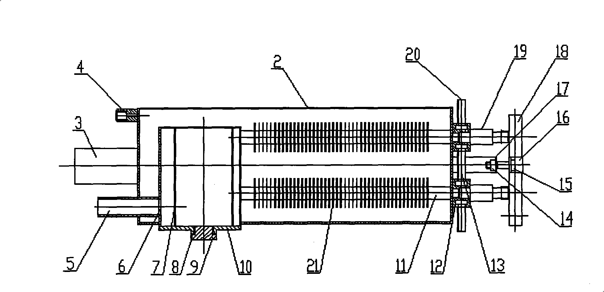
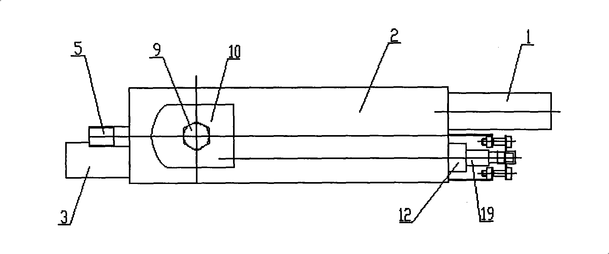
[0037] like figure 1 and figure 2 As shown, the methanol flow pipeline of the methanol cracking gas device is arranged in the cracking gas device shell 2, and its structure is: one end of the rear exhaust pipe 1 is set on the cracking gas device shell 2, and the methanol The nozzle 19 communicates with the catalytic converter outer cylinder 6 through the preheating pipe 11 in the shell 2 of the cracking gas device, and the cracking gas outlet pipe 5 is set on the catalytic converter outer cylinder 6, and the cracking gas outlet pipe 5 is connected from the cracking gas device. One end of the front exhaust pipe 3 is arranged on the shell 2, which leads to the cracked gas device shell 2 and is connected to the fuel injection system of the engine.

[0038]The methan...

Embodiment 2

[0044] The outer surface of the preheating pipe 11 is provided with a plurality of heat transfer fins 21 with good thermal conductivity.

[0045] Through this embodiment, the heat transfer effect of the preheating pipe is improved. The heat transfer fins 21 are integrated with the preheating tube 11 by welding or other techniques.

Embodiment 3

[0047] One end of the front exhaust pipe 3 is set on the cracked gas device shell 2, and a temperature sensor joint 4 is established. A temperature sensor is established on the temperature sensor joint 4, and is connected with the engine electronic control unit through a signal line.

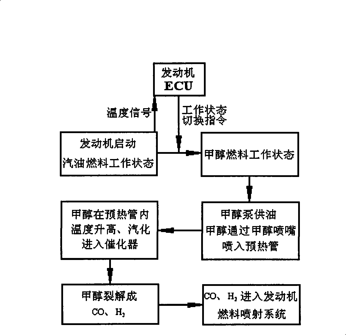
[0048] Through the signal sent by the temperature sensor and the control command of the engine ECU, the system can conveniently and flexibly switch the mode of the working state, and make the engine switch from the gasoline working state to the methanol fuel working state according to the set conditions.


PUM


Abstract

The present invention belongs to the technical field of a vehicle power system and relates to an internal-combustion engine fuel supply technology. The present invention discloses a vehicle methanol pyrolysis gas device which is arranged at the exhaust pipeline of an engine that means a pyrolysis gas device casing is one part of the exhaust pipeline. The two ends of the pyrolysis gas device casing are provided with a front exhaust pipe and a back exhaust pipe. The high-temperature exhausted by an engine cylinder enters into the pyrolysis gas device casing through the front exhaust pipe and is exhausted from the back exhaust pipe. After the technical proposal is adopted, the thermal value after the reaction is higher, and dynamic performance is kept at higher level, which improves automobile exhausting performance and fuel economic performance and satisfies the running power requirement of the whole vehicle. The present invention has simple structure and convenient use, which solves the problem of using reproducible energy source to substitute oil fuel, is better for relieving the intense situation of oil energy source and is cleaner and more protective to environment. The vehicle methanol pyrolysis gas device has reasonable control method and the flexible conversion of working states.

Description

technical field [0001] The invention belongs to the technical field of vehicle power systems, and relates to fuel supply technology for internal combustion engines. More specifically, the invention relates to a methanol cracking gas device for vehicles. In addition, the present invention also relates to the control method adopted by the device. Background technique [0002] Methanol has a good development prospect as an alternative fuel because of its renewability, cleanness and environmental protection. The combustion characteristics of pure methanol are well known. However, if it is directly used on the vehicle engine, there are still problems such as cold start difficulties. After methanol is cracked, carbon monoxide and hydrogen are generated, which can realize rapid combustion in the engine, and the thermal efficiency is greatly improved under medium and low load conditions; and exhaust waste heat is recovered to make full use of energy. Used in the methanol cracking...

Claims


Application Information

Patent Timeline
Patent Type & Authority Applications(China)
IPC IPC(8): F02M25/10
CPCY02T10/121Y02T10/12
Inventor 赵新峰
Owner CHERY AUTOMOBILE CO LTD
Why Eureka
Try Eureka