Flow-control valve for throttling hydraulic pressure medium

A flow control valve, pressure medium technology, applied in the direction of controlling the pressure of the lubricant, the device for absorbing fluid energy of the valve, the pressure lubricant, etc., can solve the problems of insignificant cost factors and so on

Inactive Publication Date: 2008-09-24
SCHAEFFLER TECH AG & CO KG
View PDF4 Cites 4 Cited by
  • Summary
  • Abstract
  • Description
  • Claims
  • Application Information

AI Technical Summary

Problems solved by technology

However, said sealing plugs, which are produced and installed solely for sealing purposes, in connection with the opening contours of the pressure medium channels, which depend solely on the sealing plugs, are usually produced in the machine housing or in particular Not insignificant cost factors may result when producing internal combustion engines

Method used


Image

  • Flow-control valve for throttling hydraulic pressure medium
  • Flow-control valve for throttling hydraulic pressure medium
  • Flow-control valve for throttling hydraulic pressure medium

Examples


Embodiment Construction

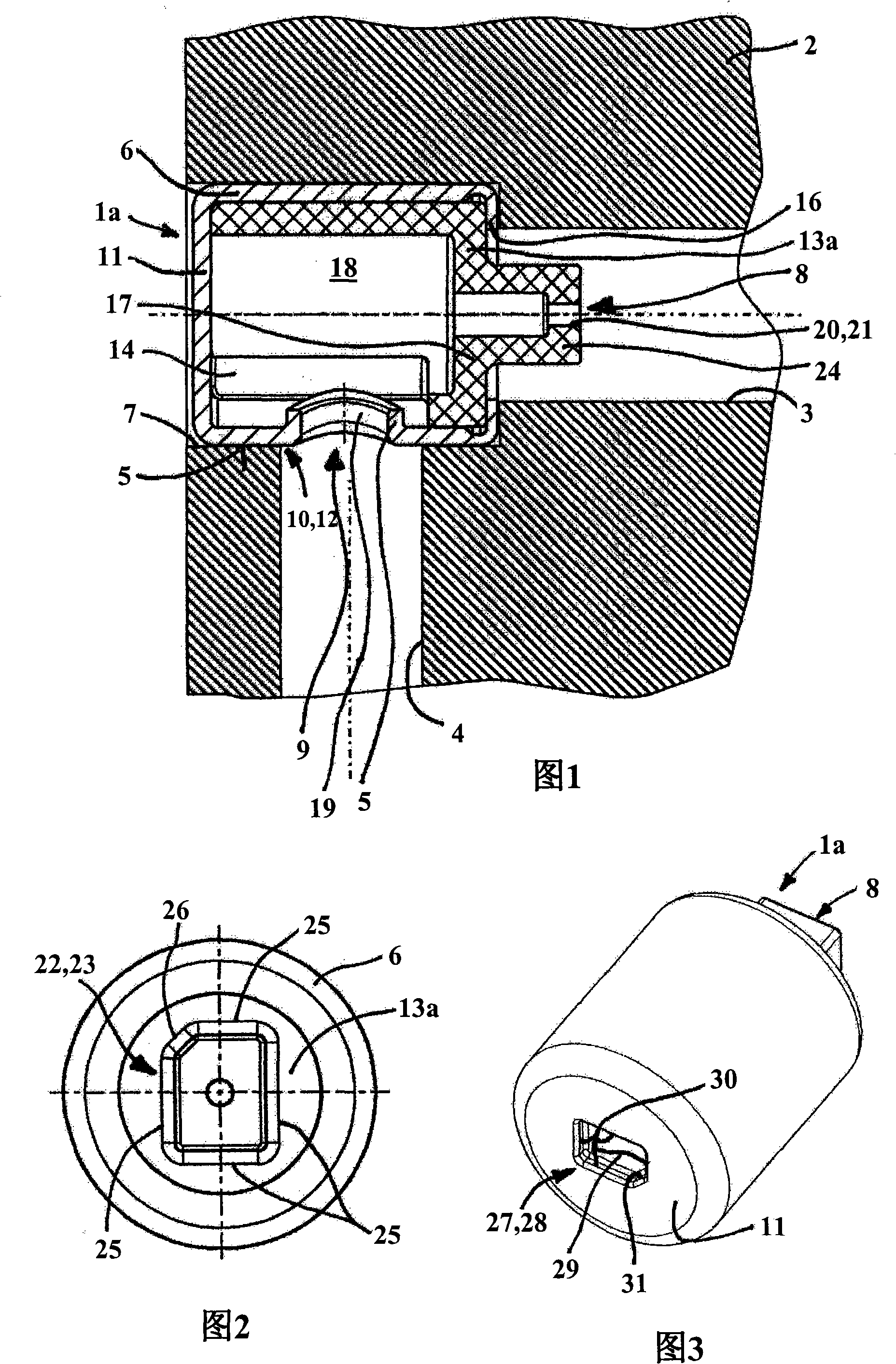
[0018] FIG. 1 shows a first embodiment variant of a flow control valve 1 a according to the invention. The figure shows a machine housing 2 with a pressure medium channel 3 formed in the form of a deep bore, into which a pressure medium channel 4 also opens transversely. The flow control valve 1a is seated in the channel 3 by means of a longitudinal force fit between the cylindrical housing surface 5 of the valve housing 6 and the diametrically widened opening 7 of the pressure medium channel 3 in such a way that: On the side facing away from the opening 7 , a first pressure medium connection 8 is connected to the pressure medium channel 3 , while a second medium connection 9 extending radially through the housing shell surface 5 is connected to the further pressure medium channel 4 . The end 10 of the valve housing 6 facing the opening 7 and adjacent to the second medium connection 9 has a closed housing bottom 11 and is hydraulically sealed to the pressure medium channel 4 b...


PUM


Abstract

The invention relates to a flow-control valve (1 a, 1 b) for throttling a hydraulic pressure medium. Said flow-control valve (1 a, 1 b) is mounted with an outer envelope surface (5) of a valve housing (6) in a pressure medium channel (3) of a machine housing (2) comprising a plug (12) which is sealed from the pressure medium, on the mouth (7) of the pressure medium channel (3), close to the machine housing (2), and comprises a first pressure medium connection (8) on a side opposing the mouth (7). The plug (12) is formed by the flow-control valve (1 a, 1 b), a second pressure medium connection (9) extending radially through the outer envelope surface (5) and being connected to another pressure medium channel (4) which transversally merges into the original pressure medium channel (3).; An end section (10) of the valve housing (6), facing the mouth (7), comprises a closed housing bottom (11) and is inserted into the pressure medium channel (3) by means of a hydraulically sealing longitudinal press fit.

Description

technical field [0001] The invention relates to a flow control valve with a throttle cross-section for throttling a hydraulic pressure medium, in particular in a lubricant circuit of an internal combustion engine. The flow control valve is mounted via the substantially cylindrical outer surface of the valve housing in the pressure medium channel of the machine housing at the opening of the pressure medium channel into the periphery of the machine housing A pressure-medium-tight sealing plug is provided, and the flow control valve has a first pressure-medium connection connected to the pressure-medium channel on the side remote from the opening. Background technique [0002] Flow control valves of this type are known as throttling devices in hydraulic systems and hydraulic control systems and are intended to supply a hydraulic medium under pressure with a reduced volume flow to a hydraulic load. In the field of internal combustion engines, flow control valves of this type ca...

Claims


Application Information

Patent Timeline
Patent Type & Authority Applications(China)
IPC IPC(8): F01M1/16
CPCF16K5/0414F01M1/16F16K47/06F16N27/005F01M1/06
Inventor 赖纳·富尔曼安德烈·丁斯特比尔斯蒂芬·基宁格
Owner SCHAEFFLER TECH AG & CO KG
Why Eureka
Try Eureka