Atmosphere controlled joint device, method and electronic device

A technology of a bonding device and a bonding method, which is applied in the direction of assembling printed circuits, circuits, and welding equipment with electrical components, can solve problems such as component damage, and achieve the effects of reducing the bonding pressure, realizing the bonding temperature, and suppressing the deterioration of electrical characteristics.

Inactive Publication Date: 2012-07-25
大见忠弘
View PDF1 Cites 0 Cited by
  • Summary
  • Abstract
  • Description
  • Claims
  • Application Information

AI Technical Summary

Problems solved by technology

However, static electricity will be generated in this dry atmosphere, leading to the destruction of components

Method used


Image

  • Atmosphere controlled joint device, method and electronic device
  • Atmosphere controlled joint device, method and electronic device
  • Atmosphere controlled joint device, method and electronic device

Examples


Embodiment Construction

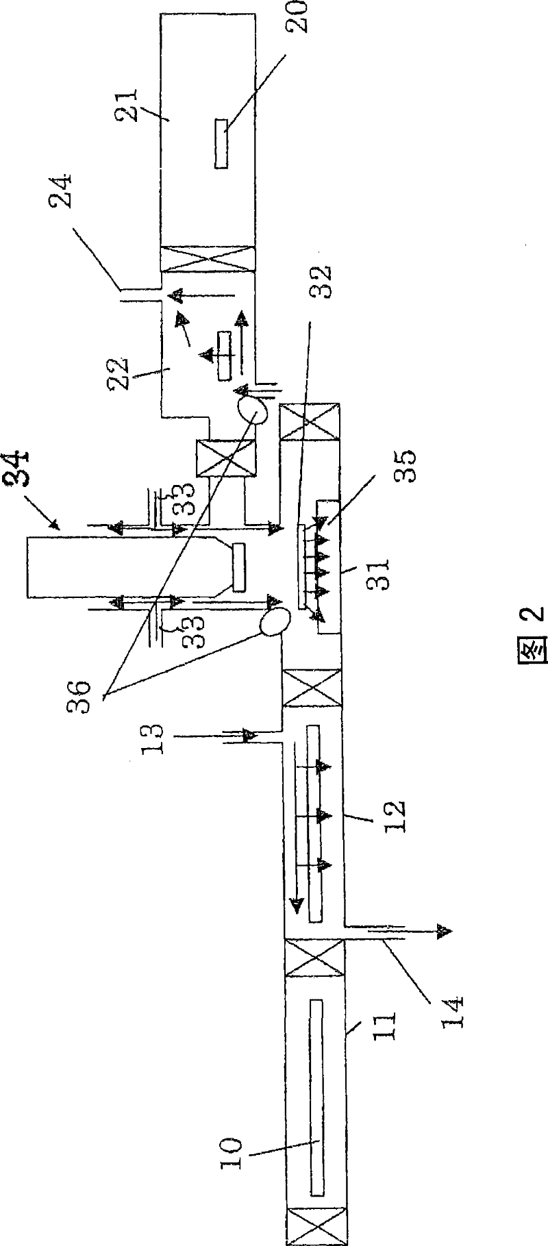
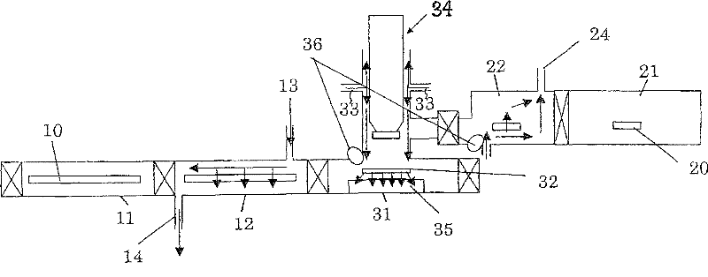
[0022] Regarding the bonding device of the embodiment of the present invention, the use figure 2 Be explained. figure 2 It is a schematic diagram showing the structure of the bonding apparatus of this embodiment. The mounting substrate 10 is introduced from the substrate introduction chamber 11, and the dry inert gas 13 is introduced into the substrate surface adsorption moisture removal chamber 12 to remove moisture.

[0023] On the other hand, the component 20 to be mounted on the mounting substrate 10 is introduced from the component introduction chamber 21 into the component surface adsorption moisture removal chamber 22, and the moisture on the surface is removed by dry inert gas. Both are crimped in a crimping chamber 31 having a crimping arm 34 and a crimping table 35 .

[0024] The bonding apparatus has a substrate conveyance mechanism not shown, a component conveyance mechanism not shown similarly, and a substrate carry-out chamber not shown. In the substrate surf...


PUM


Abstract

This invention provides a joining device for pressure welding a pressure welding part that can realize pressure welding under low temperature and low pressure conditions by rendering the moisture content of the pressure welding part atmosphere within the device relatively smaller than the moisture content of the atmosphere outside the device. In this case, the amount of water adsorbed on each surface of a joining metal terminal and a metal terminal to be joined constituting the pressure welding part is brought to not more than 1 10<16> molecules / cm<2>.

Description

technical field [0001] The present invention relates to a joining device which must be used in the manufacture, especially in the installation, of electronic devices. More specifically, it relates to bonding such as wire bonding and flip-chip bonding for electrically connecting terminals on electronic components such as semiconductor chips and terminals for external lead-out, and connecting electronic components such as semiconductor components and capacitors to printed wiring. Bonding devices and bonding methods used for crimping metal terminals and electrical bonding when mounting on mounting substrates such as boards and package substrates. Such bonding methods include mounting to FPC (Flexible Printed Circuit), TAB (Tape Automated Bonding), wire bonding, wire-free bonding such as flip chip, and the like. Background technique [0002] In recent years, with the advancement of miniaturization, high functionality, and high performance of electronic devices such as mobile ph...

Claims


Application Information

Patent Timeline
Patent Type & Authority Patents(China)
IPC IPC(8): H01L21/60H05K3/32
CPCH01L2924/0105H01L2924/01082H01L2924/01004H01L2924/01049B23K20/10H01L2224/81203H01L2224/81801H01L2924/01029H01L21/67144H01L24/78H01L2224/75H01L2924/19041H01L2224/81205H01L2224/78H01L2924/014H01L2924/01013H01L2924/01024B23K20/004H01L2224/85H01L2924/0103H01L24/85H01L2924/01047H01L24/81H01L2924/01079H01L2924/01005H01L2924/01033H01L2924/01006B23K20/02H01L24/75H01L2924/3025B23K2201/40B23K2101/40H01L2924/00014H01L2224/48H01L2224/45099H05K3/32
Inventor 大见忠弘森本明大
Owner 大见忠弘
Why Eureka
Try Eureka