
Fluid-filled type vibration damping device and method of manufacturing the same

一种减振装置、流体填充的技术,应用在减振器、动力装置、喷气推进装置等方向,能够解决分开、肉眼检查评价预处理质量、粘合缺陷等问题

Active Publication Date: 2008-10-01
SUMITOMO RIKO CO LTD
View PDF3 Cites 3 Cited by
  • Summary
  • Abstract
  • Description
  • Claims
  • Application Information

AI Technical Summary

Problems solved by technology

Inherent problem is that in the subsequent vulcanization forming of the sealing rubber layer, the untreated part is prone to cause adhesion defects
[0009] In particular, after treatment, it is difficult to assess the quality of the pretreatment performed on the second mounting member simply by visual inspection
[0010] Also, since a plurality of second mounting members are subjected to pretreatment in a state of being put into a single basket, during processing, fitting parts that are not fitted together before processing may be fitted together; and After handling, secondary mounting members that fit together during handling may separate

Method used


Image

  • Fluid-filled type vibration damping device and method of manufacturing the same
  • Fluid-filled type vibration damping device and method of manufacturing the same
  • Fluid-filled type vibration damping device and method of manufacturing the same

Examples


Embodiment Construction

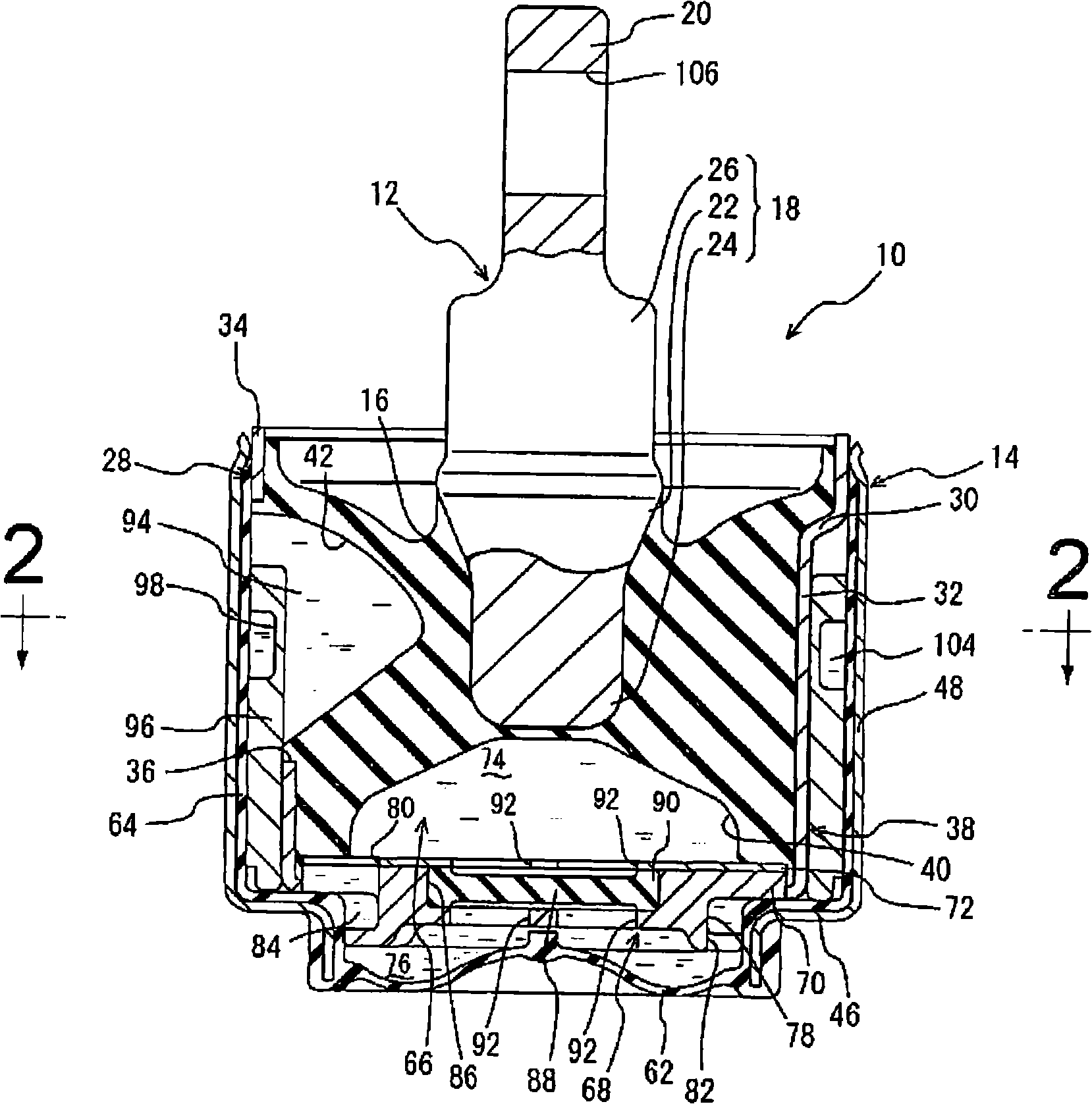
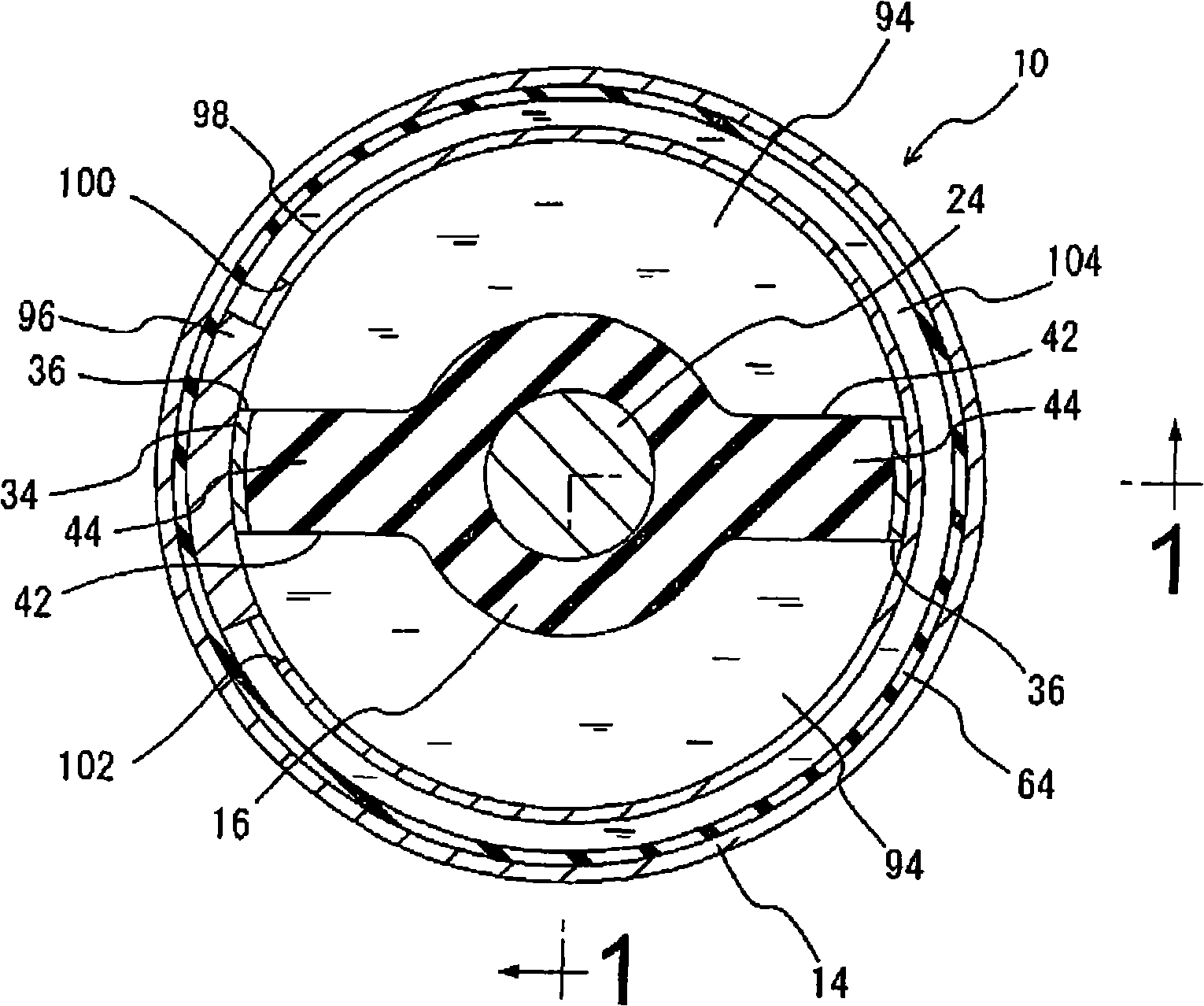
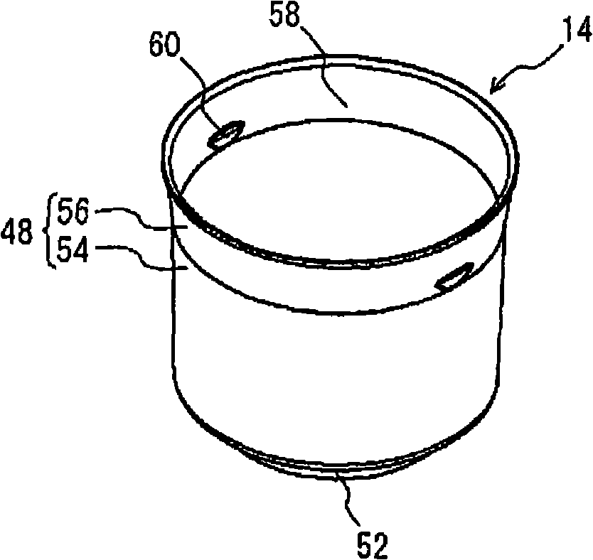
[0045] figure 1 and figure 2 A vehicle engine mount 10 is shown as a fluid-filled vibration damping device according to an embodiment of the present invention. This engine mount 10 has a structure in which a metal inner shaft member 12 serving as an inner mounting member and a metal outer cylindrical member 14 serving as an outer cylindrical mounting member are positioned to be spaced apart from each other, and the inner shaft member 12 and the outer cylinder The shape members 14 are connected by a main rubber elastic body 16 . The inner shaft member 12 is mounted to the power plant of the vehicle, while the outer cylindrical member 14 is mounted to the vehicle body to provide vibration-damping support of the power plant on the vehicle body. exist figure 1 The engine mount 10 of the present embodiment is installed in an orientation in which the vertical direction is substantially aligned with the vertical direction. Here, the vertical direction in principle means figure ...


PUM


Abstract

A fluid filled type vibration damping device wherein an outer tubular mounting member is externally fitted onto the collar sleeve at an externally fitted section formed by a tapered tube portion of the outer tubular mounting member, by means of a diameter reduction process. A mating projection projecting diametrically inward is formed on an inside peripheral face of the outer tubular mounting member, while a seal rubber layer having a thickness greater than a projecting height of the mating projection is formed covering the inside peripheral face of the outer tubular mounting member with the mating projection covered by the seal rubber layer. A location and projecting height of the mating projection are arranged so as to prevent an entry of another outer tubular mounting member into a large-diameter opening of the tapered tube portion during pre-treatment.

Description

technical field [0001] The present invention relates to a fluid-filled vibration-damping device adapted to exert a vibration-damping effect based on the flow action of a non-compressible fluid filled therein. More particularly, the present invention relates to a fluid-filled vibration damping device applicable to vehicle engine mounts and the like, and a method of manufacturing the same. Background technique [0002] As a vibration-damping coupling body or a vibration-damping support body designed to be installed between components constituting a vibration transmission system, it is known in the prior art to exert a damping effect based on a flow action such as a resonance effect of a non-compressible fluid sealed inside. Fluid-filled damping device with vibration effect. [0003] This type of fluid-filled vibration damping device disclosed in Patent Document 1 (US Patent No. 7,044,455) has: a first metal mounting member anchored to a central portion of a main rubber elasti...

Claims


Application Information

Patent Timeline
Patent Type & Authority Applications(China)
IPC IPC(8): F16F13/04F16F15/023F16F5/00B60K5/12
CPCF16F13/10Y10T29/49615
Inventor 西直树
Owner SUMITOMO RIKO CO LTD
Learn More