Nitrogen gas conveying device

A nitrogen delivery and liquid nitrogen storage tank technology, applied in boiling devices, fixed-capacity gas storage tanks, gas/liquid distribution and storage, etc., can solve the problem of large loss of liquid nitrogen, damage to pipelines, and increase the extra work of workers load and other problems, to achieve the effect of improving the evaporation effect and the cooling effect

Inactive Publication Date: 2008-10-01
SUZHOU GUANDA MAGNET
View PDF0 Cites 4 Cited by
  • Summary
  • Abstract
  • Description
  • Claims
  • Application Information

AI Technical Summary

Problems solved by technology

The disadvantage of the above-mentioned nitrogen delivery device is that since the temperature of liquid nitrogen is usually around -184°C, a thick layer of ice is often formed on the pipeline 3 connecting from the liquid nitrogen storage tank 1 to the evaporator 2, The gasification effect of the evaporator is poor, and the worse the gasification effect, the greater the unreasonable loss of liquid nitrogen
However, artificially deicing the pipeline 3 will increase the extra workload of the workers on the one hand, and on the other hand frequent ice breaking will damage the pipeline 3, especially affecting the sealing connection between the pipeline 3 and the liquid nitrogen storage tank 1 , burying the risk of leakage
Therefore, practice has proved that this artificial method of deicing the pipeline 3 is unsafe and unscientific, so it is not advisable
[0003] The above problems have plagued the industry for a long time, and there is no good countermeasure

Method used


Image

  • Nitrogen gas conveying device
  • Nitrogen gas conveying device

Examples


Embodiment 1

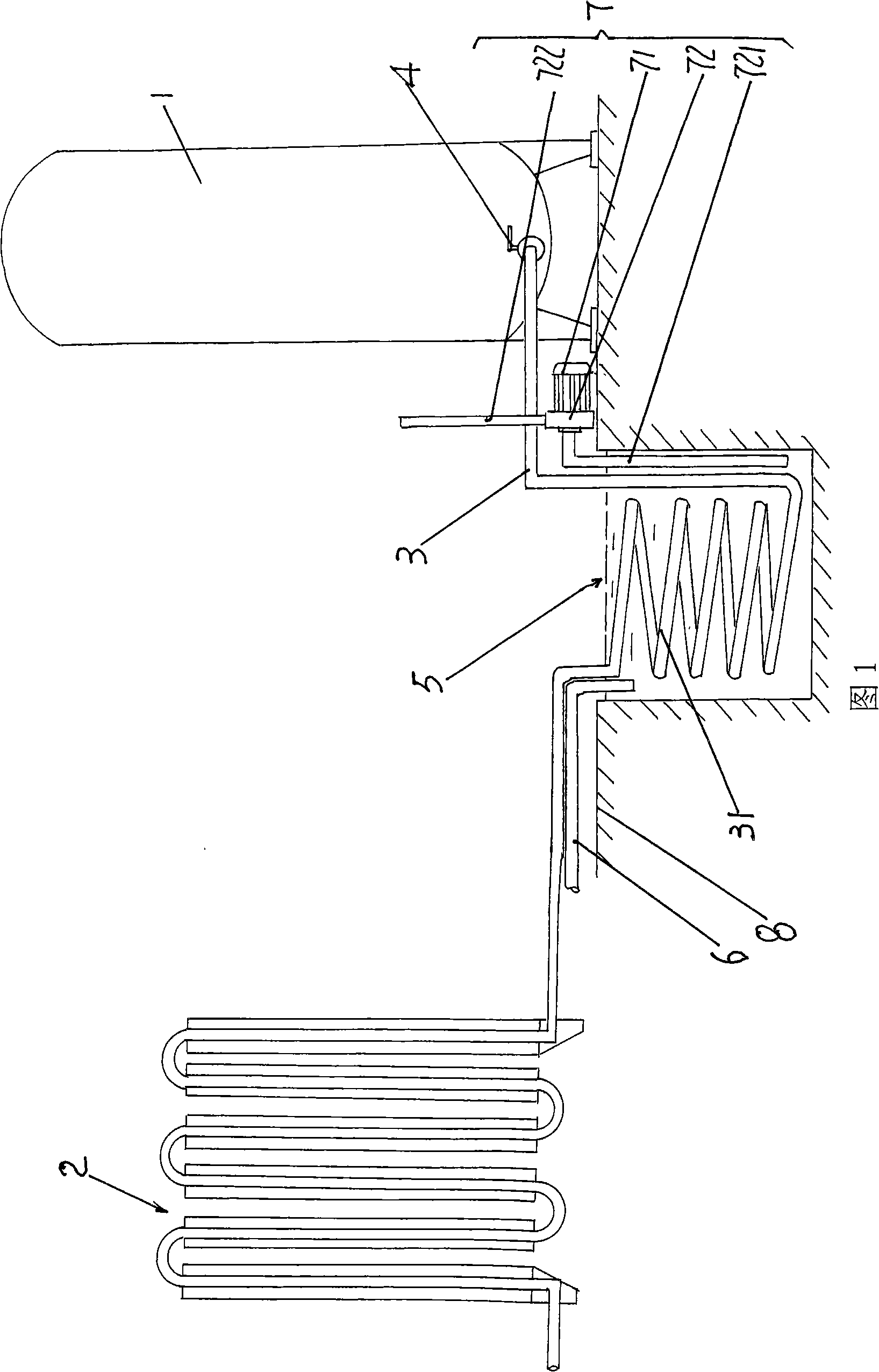
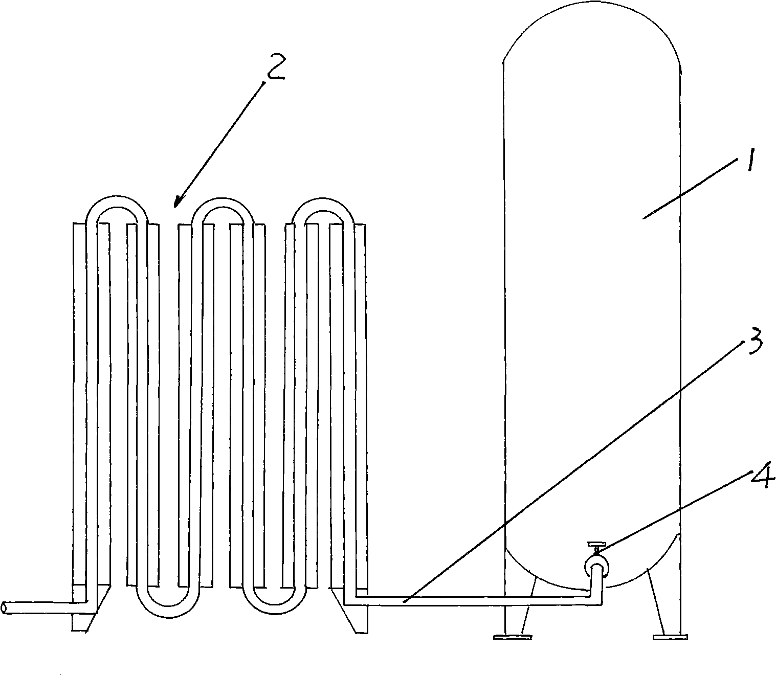
[0017] Please see Figure 1. Under normal circumstances, the liquid nitrogen storage tank 1 and the evaporator 2 are installed and fixed on the outdoor floor 8. One end of the pipeline 3 is connected to the liquid nitrogen storage tank 1, and the other end is connected to the evaporator 2. , open the valve 4, the liquid nitrogen in the liquid nitrogen storage tank 1 can be introduced into the evaporator 2 for evaporation through the pipeline 3, and the evaporation of the evaporator 2 makes the liquid nitrogen into gaseous nitrogen, that is, nitrogen, and introduces it into the furnace of the sintering kiln middle.

[0018] In the technical solution recommended by the present invention, the middle part of the pipeline 3 for transporting liquid nitrogen is processed into a curved pipe section 31 , and the curved pipe section 31 is placed into the equipped heat exchange tank 5 . In this embodiment, the selected heat exchange tank 5 is directly processed on the floor 8, that is, a ...

Embodiment 2

[0020] The figure is omitted, only the curved pipe section 31 is processed into a U shape, wherein the total length of the curved pipe section 31 is the same as that of Embodiment 1, and the rest are the same as the description of Embodiment 1.

Embodiment 3

[0022] The figure is omitted, and the curved shape of the curved pipe section 31 with the same total length as that of Embodiment 1 is formed into an S shape, and the rest are the same as the description of Embodiment 1.


PUM


Abstract

A nitrogen gas delivery device belongs to the transferring technical field for protecting the gas by the nitrogen gas, which is composed of a liquid nitrogen tank, an evaporator and a pipe. One end of the pipe is connected with the liquid nitrogen tank, the other end of which is connected with the evaporator. The middle part of the pipe has a bent pipe input into the heat exchange groove, which is provided with a hot water inlet pipe for heat exchange, and the heat exchange groove is provided with a cooling water circulation mechanism. The device has the advantages that, due to the heat exchange inducted into the evaporator through the heat exchange groove of the bent pipe of the middle part, the evaporating effect of the evaporator can be increased, compared with the existing art 15-20% liquid nitrogen can be saved; on freezing occurs on the whole pipe, so on man is needed to deice; the cooled water through the bent pipe heat exchange is returned to the sintering kiln for circulating cooling, which is favorable for the cooling effect of the sintering kiln.

Description

technical field [0001] The invention belongs to the technical field of conveying nitrogen protective gas, and in particular relates to a nitrogen conveying device, which is used for sending liquid nitrogen in a liquid nitrogen storage tank into a kiln after being vaporized by an evaporator. Background technique [0002] For ferrite, electronic ceramics or other similar products that need to be sintered under nitrogen protective gas, nitrogen gas is usually delivered to the sintering furnace. For this reason, the manufacturers of the above products are equipped with nitrogen gas delivery devices. Nitrogen gas delivery devices The structure is very simple, such as figure 2 As shown, it consists of a liquid nitrogen storage tank 1 and an evaporator 2 connected to the liquid nitrogen storage tank 1 through a pipeline 3. When in use, the valve 4 on the pipeline 3 is opened, and the liquid nitrogen in the liquid nitrogen storage tank 1 is released by the pipeline. Road 3 enters t...

Claims


Application Information

Patent Timeline
Patent Type & Authority Applications(China)
IPC IPC(8): F17C7/04B01B1/00F28D7/10F27D7/00F27D9/00F27B9/30
Inventor 孟力张晓明
Owner SUZHOU GUANDA MAGNET
Why Eureka
Try Eureka