Gas-liquid distributor of trickle bed reactor

A gas-liquid distributor and reactor technology, used in chemical instruments and methods, petroleum industry, processing hydrocarbon oil, etc.

Active Publication Date: 2011-08-17
CHINA PETROLEUM & CHEM CORP +1
View PDF2 Cites 1 Cited by
  • Summary
  • Abstract
  • Description
  • Claims
  • Application Information

AI Technical Summary

Problems solved by technology

[0007] The technical problem to be solved by the present invention is that the gas-liquid distribution in the trickle bed reactor in the prior art is uneven, resulting in uneven distribution of fluid in the catalyst bed, trickle flow In order to solve the problems of poor effect and poor catalytic reaction efficiency, a new gas-liquid distributor for trickle bed reactor is provided

Method used


Image

  • Gas-liquid distributor of trickle bed reactor
  • Gas-liquid distributor of trickle bed reactor
  • Gas-liquid distributor of trickle bed reactor

Examples


Embodiment 1

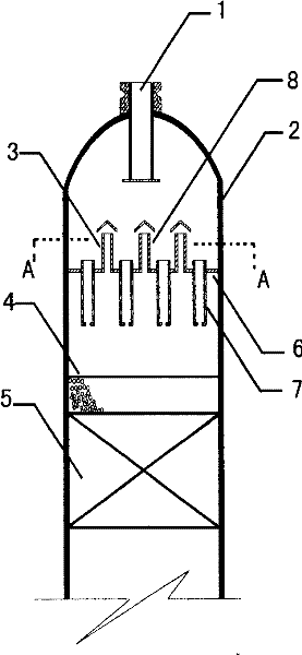
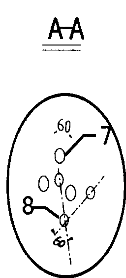
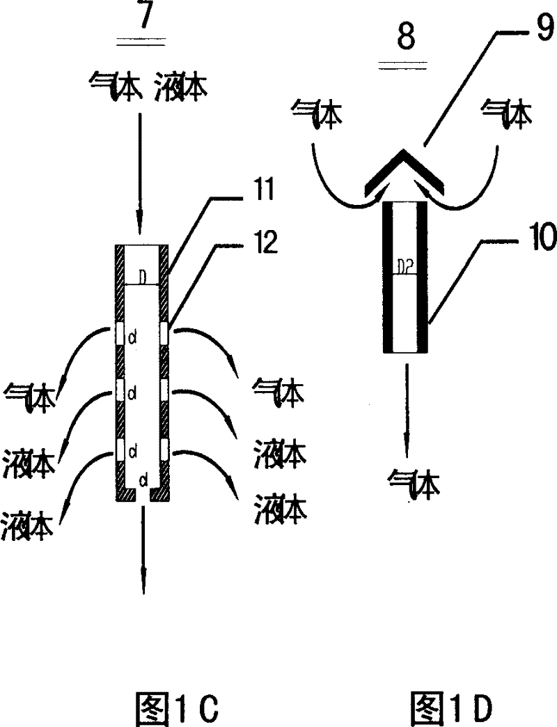
[0024] As shown in Figure 1, the initial pyrolysis gasoline C 5 ~C 9 Fractions (oils) with a diene value greater than 25 g I 2 / 100 grams of Oil, hydrogen enters the trickle bed reactor with a hydrogen-oil ratio equal to 100, the catalyst adopts a general-purpose palladium series hydrogenation catalyst, adopts the gas-liquid distributor of the present invention, and the upper end of the short pipe 11 stretches out from the top of the distribution plate 6 for 50 mm, the lower end protrudes 500 mm below the distribution plate 6, the ratio of the diameter d of the small hole 12 to the inner diameter D of the liquid channel pipe 7 is 0.015: 1.0, and the area S of all the small holes 12 1 and the area S of the inner cross-section of the liquid channel tube 7 2 The ratio of the ratio is 1.01:1.0; the opening ratio of the gas passage pipe 8 on the distribution plate 6 is 15%, and the opening ratio of the liquid passage pipe 7 on the distribution plate 6 is 20%. Experiments have pr...

Embodiment 2

[0026] As shown in Figure 1, the initial pyrolysis gasoline C 5 ~C 9 Fractions (oils) with a diene value greater than 30 g I 2 / 100 grams of Oil, hydrogen enters the trickle bed reactor with a hydrogen-oil ratio equal to 100, the catalyst adopts a general-purpose palladium series hydrogenation catalyst, adopts the gas-liquid distributor of the present invention, and the upper end of the short pipe 11 stretches out from the top of the distribution plate 6 25 mm, the lower end stretches out 800 mm below the distribution plate 6, the ratio of the diameter d of the small hole 12 to the inner diameter D of the liquid channel pipe 7 is 0.011: 1.0, the area S of all the small holes 12 1 and the area S of the inner cross-section of the liquid channel tube 7 2 The ratio of the ratio is 0.95:1.0; the opening ratio of the gas passage pipe 8 on the distribution plate 6 is 10%, and the opening ratio of the liquid passage pipe 7 on the distribution plate 6 is 15%. Experiments have proved...

Embodiment 3

[0028] As shown in Figure 1, the initial pyrolysis gasoline C 5 ~C 9 Fractions (oils) with a diene value greater than 20 g I 2 / 100 gram of Oil, hydrogen enters the trickle bed reactor with a hydrogen-oil ratio of 100, the catalyst adopts a general-purpose palladium series hydrogenation catalyst, adopts the gas-liquid distributor of the present invention, and the upper end of the short pipe 11 stretches out 80 above the distribution plate 6 mm, the lower end extends 650 mm below the distribution plate 6, the ratio of the diameter d of the small hole 12 to the inner diameter D of the liquid channel pipe 7 is 0.15:1.0, and the area S of all the small holes 12 1 and the area S of the inner cross-section of the liquid channel tube 7 2 The ratio of the ratio is 1.1:1.0; the opening ratio of the gas passage pipe 8 on the distribution plate 6 is 20%, and the opening ratio of the liquid passage pipe 7 on the distribution plate 6 is 30%. Experiments have proved that the diene value o...


PUM

PropertyMeasurementUnit
porosityaaaaaaaaaa
porosityaaaaaaaaaa

Abstract

The invention relates to a liquid-gas distributor of a trickle-bed reactor, which aims at solving the problems that the uneven liquid-gas distribution of the trickle-bed reactor in the prior art results in the uneven fluid distribution inside the layer of a catalyst bed; the trickling effect is not good; and the efficiency of the catalytic reaction is not well. The liquid-gas distributor adopts the following technical scheme: the liquid-gas distributor is provided with a gas passage pipe and a liquid passage pipe on a distributing plate; the gas passage pipe is composed of a cone roof and a straight nozzle stub; the liquid passage pipe is a vertical nozzle stub with the upper end extending 10 to 100mm out of the upper part of the distributing plate and the lower end extending 200 to 1000mm out of the lower part of the distributing plate; a plurality of pinholes are evenly opened on the cross section at different positions along the axial direction to form the liquid-gas distributor. The technical scheme better solves the problems, greatly improves the reaction efficiency of the trickle-bed reactor and can be applied to various trickle-bed reactors.

Description

technical field [0001] The invention relates to a gas-liquid distributor of a trickle bed reactor. Background technique [0002] Trickle bed reactor is one of the main types of reactors, because it not only has the advantages of simple structure and low equipment investment, but also has the characteristics of convenient operation and large operation flexibility. Therefore, trickle bed reactors are widely used in oil refining and chemical industry. Especially in the fields of hydrocracking of oil products and hydrofining of hydrocarbons, trickle bed is one of the most basic reactors. One of the characteristics of the trickle bed reactor is that the gas and liquid in the reactor flow through the catalyst bed in parallel, wherein the liquid flows through the catalyst bed in a trickle flow, while the gas passes through in a continuous flow. Therefore, whether the liquid can form a trickle flow in the reactor and whether the gas distribution is uniform are the main factors aff...

Claims


Application Information

Patent Timeline
Patent Type & Authority Patents(China)
IPC IPC(8): C10G49/00B01J8/04
Inventor 甘永胜何志
Owner CHINA PETROLEUM & CHEM CORP
Why Eureka
Try Eureka