Water processing reactor integrating photocatalysis and biological degradation and method thereof

A technology of biodegradation and photocatalysis, which is applied in the field of water treatment reactor and its treatment integrating photocatalysis and biodegradation, can solve the problems of reduced efficiency, increased treatment cost, and complicated treatment process, so as to change the structure, The effect of increasing speed

Inactive Publication Date: 2008-10-15
SHANGHAI NORMAL UNIVERSITY
View PDF0 Cites 16 Cited by
  • Summary
  • Abstract
  • Description
  • Claims
  • Application Information

AI Technical Summary

Problems solved by technology

On the one hand, this complicates the processing process, on the other

Method used


Image

  • Water processing reactor integrating photocatalysis and biological degradation and method thereof
  • Water processing reactor integrating photocatalysis and biological degradation and method thereof

Examples


Example Embodiment

[0038] Example 1 Treatment of refractory organic wastewater

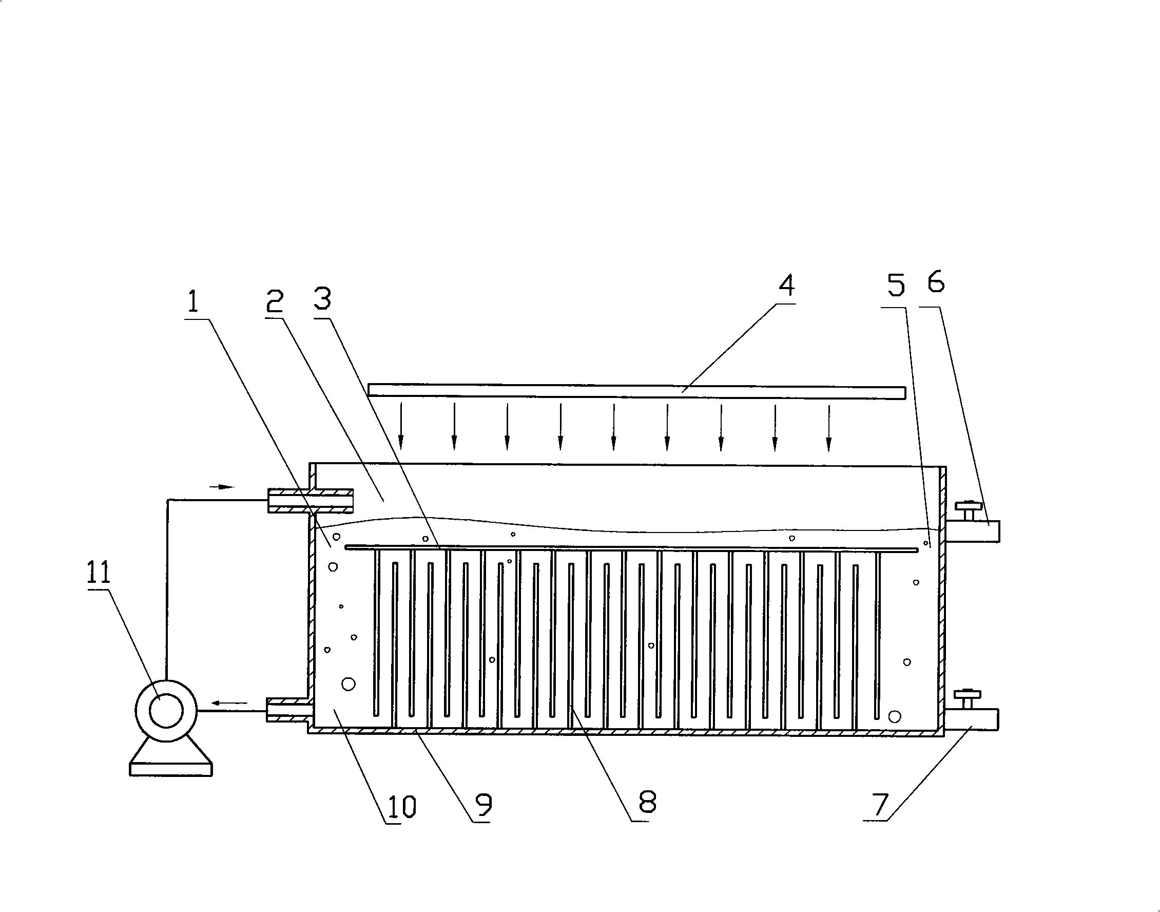
[0039] Coating TiO on the surface of ceramic materials 2 , The prepared photocatalytic plate 3 is placed horizontally in the reactor 9, and the reactor 9 is divided into an upper photocatalytic zone 2 and a lower biodegradation zone 10.

[0040] Add the domesticated activated sludge solution or the special microbial solution cultivated for the refractory organic wastewater into the reactor 9 and immerse the biofilm carrier 8, and circulate in the reactor 9, turn off the ultraviolet light source 4, after inoculation by adsorption After 2-3 days, a mature biofilm is formed, and excess activated sludge or bacterial liquid is discharged.

[0041]After the biofilm is formed, continuous treatment is carried out, another water pump is used to control the flow rate, and the water to be treated is pumped into the reactor for continuous treatment. At the same time, the water is pumped out from the lower part of the reactor 9 thro...

Example Embodiment

[0042] Example 2 Surface water remediation of compound pollution

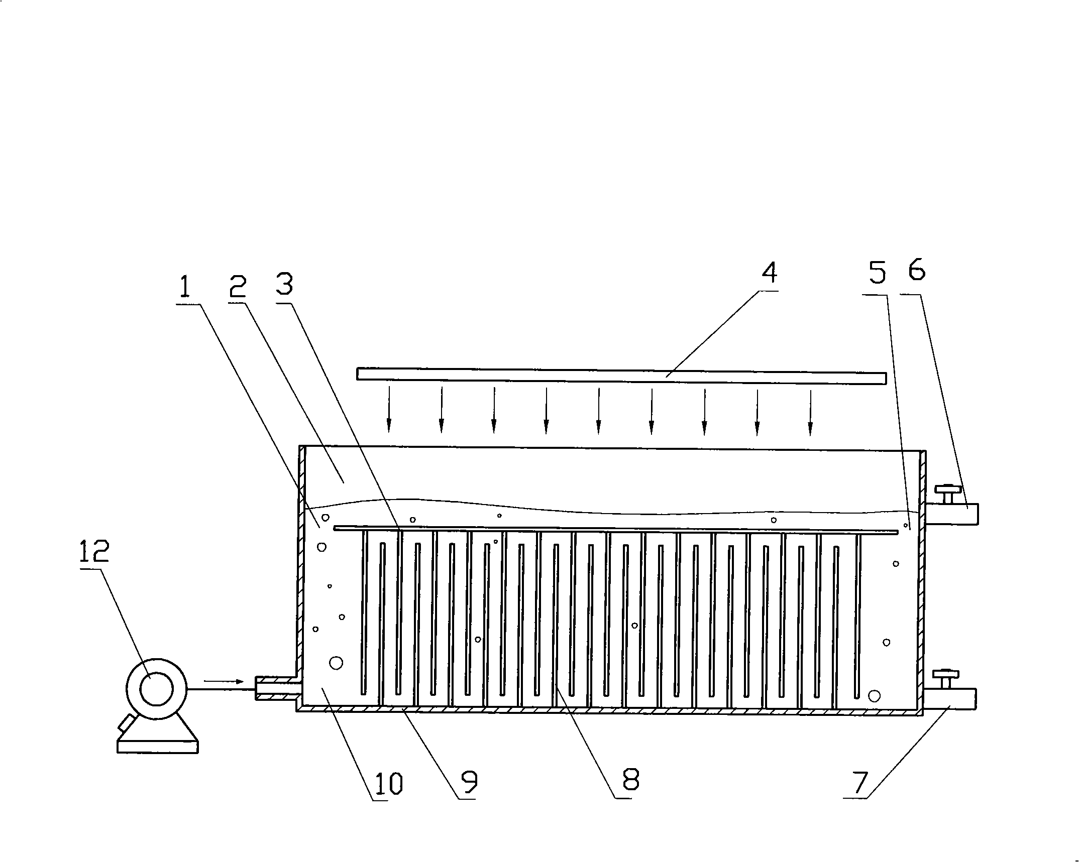
[0043] Coating TiO on the surface of ceramic or glass material 2 , The prepared photocatalytic plate 3 is placed on the upper part of the reactor 9, and the reactor 9 is divided into a photocatalytic zone 2 and a biodegradation zone 10. Introduce and operate the film according to the method described in Example 1. After the film is successfully installed, continuously pump the surface water of compound pollution for continuous treatment. The water to be treated is continuously circulated through the photocatalysis under the action of the circulating water pump 11 or the air pump 12 Zone and biological reaction zone, when the water body passes through the photocatalytic zone 2, the refractory organic pollutants are partially degraded into organic carbon sources that can be effectively used by microorganisms under the role of photocatalysis, which promotes the smooth denitrification and phosphorus removal of complex ...

Example Embodiment

[0044] Example 3 Treatment of source water

[0045] Coating TiO on the surface of ceramic or glass material 2 , The prepared photocatalytic plate 3 is placed on the upper part of the reactor 9, and the reactor 9 is divided into a photocatalytic zone 2 and a biodegradation zone 10. The water to be treated is continuously pumped into the reactor 9, the ultraviolet light source 4 is turned off, and the water is circulated in the reactor 9 through the circulating water pump 11 or the air pump 12 under the condition of no ultraviolet irradiation. After 7-14 days, let it naturally form a biofilm on the biofilm carrier 8. After the film is successfully installed, turn on the ultraviolet light source 4 to continuously and deeply treat the source water to remove trace organic pollutants in the water body.


PUM


Abstract

The invention is a water treatment reactor that integrates photocatalysis and biodegradation, and a processing method thereof. A water treatment reactor integrating photocatalysis and biodegration comprises a photocatalysis plate (3) as the baffle plate between a photocatalysis section (2) at the upper part of the reactor and a biodegradation section (10) at the lower part of the reactor; an upper water hole (1) and a lower water hole (5) are opened on the photocatalysis plate; an ultraviolet source (4) is controlled by a switch and is positioned above the photocatalysis plate (3); a biomembrane carrier (8) is positioned in the biodegradation section (10); a water outlet (6) and a valve are opened on the vessel wall at the lower edge of the photocatalysis section (2); a water circulation device is arranged on the reactor (9); the photocatalysis plate shields the microbes in the biodegradation section to protect the microbes from the harm by ultraviolet light; under the joint action of the photocatalyst and the biomembrane, the organic matter that is hard to degrade can greatly increase the rate of water treatment. The reactor is characterized in compact device structure, high efficiency and high speed.

Description

(1) Technical field [0001] The invention relates to a water treatment technology, including a reactor and a method thereof, in particular to a water treatment reactor integrating photocatalysis and biodegradation and a treatment method thereof. (2) Background technology [0002] The technology belongs to a device and a method for environmental engineering, biochemical reaction engineering, environmental biotechnology, chemical reaction engineering and water treatment. With the continuous development of industrial and agricultural production and the continuous improvement of people's living standards, many natural rivers, lakes, landscape waters and other surface waters, and even drinking water sources have been polluted, and most of them have more or less formed eutrophication. Coupled with the random discharge of some industrial wastewater, many water bodies also contain a large amount of refractory organic pollutants, forming complex pollution. These pollutions lead to th...

Claims


Application Information

Patent Timeline
IPC IPC(8): C02F1/32C02F3/12
CPCY02W10/10
Inventor 张永明阎宁王磊邹贞
Owner SHANGHAI NORMAL UNIVERSITY
Why Eureka
Try Eureka