Engine system and control method of the engine

A control method and engine technology, applied in the direction of engine control, engine starting, engine components, etc., can solve problems such as engine quality or reliability, and achieve the effect of improving quality

Inactive Publication Date: 2008-10-15
MAZDA MOTOR CORP
View PDF1 Cites 10 Cited by
  • Summary
  • Abstract
  • Description
  • Claims
  • Application Information

AI Technical Summary

Problems solved by technology

This creates problems with e

Method used


Image

  • Engine system and control method of the engine
  • Engine system and control method of the engine
  • Engine system and control method of the engine

Examples


no. 1 approach

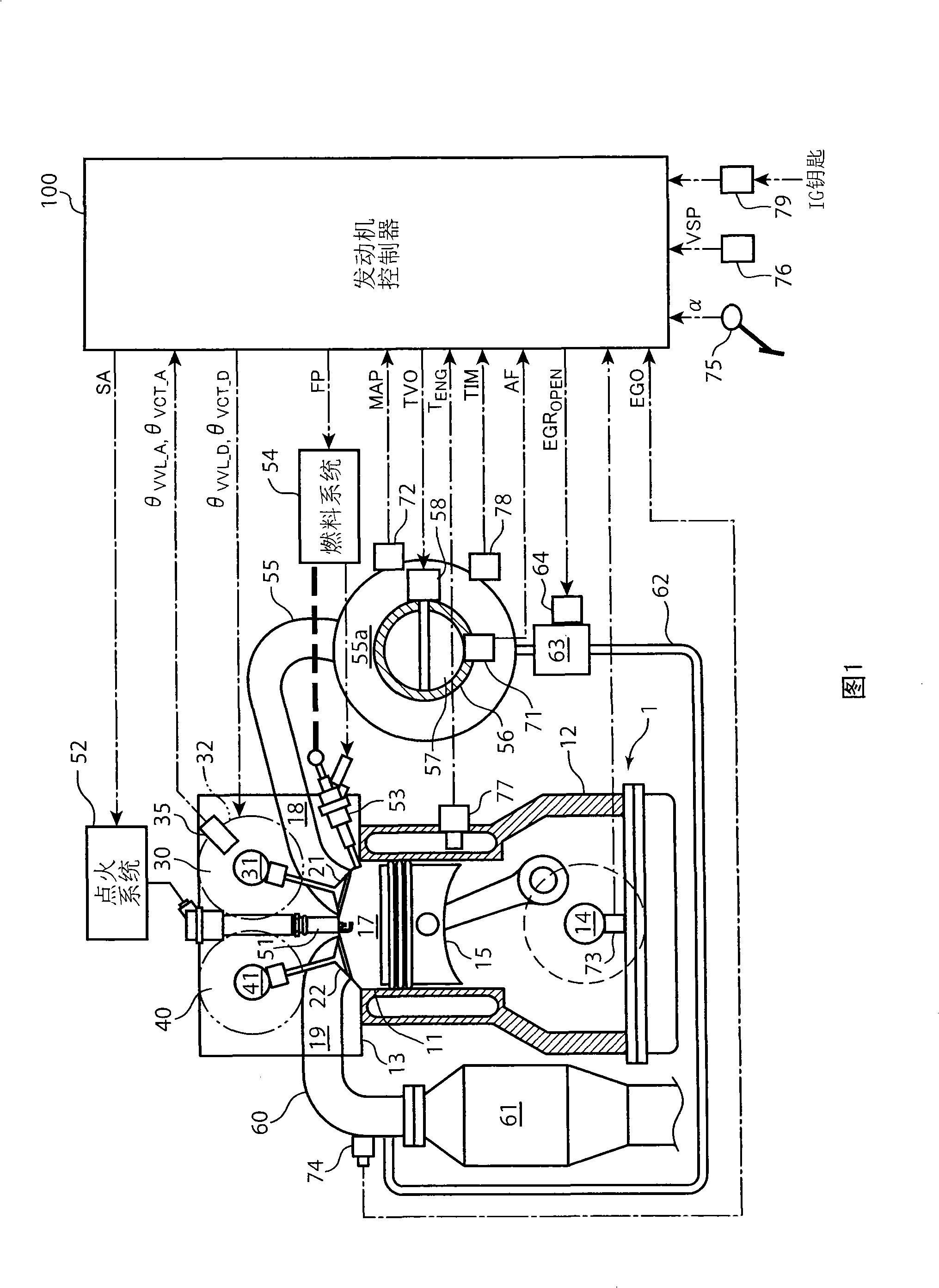
[0045] Fig. 1 schematically shows the overall structure of an engine system to which the present invention is applied. This engine system includes an engine 1 as an internal combustion engine, and an engine controller 100 as a control device for controlling various actuators attached to the engine 1 .

[0046] The engine 1 is a 4-cycle spark ignition internal combustion engine loaded on vehicles such as automobiles, and its output shaft can be connected with the drive wheels through a drive system including a transmission to drive the vehicle. The engine 1 includes a cylinder bank 12 and a cylinder head 13 placed thereon. A plurality of cylinders 11 are formed inside both the cylinder bank 12 and the cylinder head 13 . The engine 1 is, for example, an inline 4-cylinder engine for driving a vehicle, and includes four cylinders 11 . On the other hand, in the cylinder group 11 , the crankshaft 14 is rotatably supported by radial bearings or the like.

[0047] A piston 15 is sl...

no. 2 approach

[0096] Refer below Figure 7 and Figure 8 Control in the second embodiment will be described.

[0097] Figure 7 A routine for overall control of the engine 1 is shown. Initially, the launch control flag F is determined in step S31 发动 Whether the value (initial value: 0) is 1. This determination is set to No, that is, the launch control flag F 发动 When the value is 0, the following control during normal operation is performed.

[0098] First, various signals such as the depression amount α of the accelerator pedal are read (step S32). Next, according to the read accelerator pedal depression amount α, the rotational speed N of the engine 1 ENG (Number of revolutions per unit time, the same below), vehicle speed VSP to calculate the target torque TQ D (step S33), according to the calculated target torque TQ D and engine 1 speed N ENG Calculation of fuel injection amount FP, target air charge amount CE D , and ignition timing SA (step S34).

[0099] Next, according to...


PUM


Abstract

Methods and systems for controlling an internal combustion engine are provided. The method may include opening and closing an intake valve respectively at first opening and closing timings of a cylinder cycle during an engine start when a temperature of the internal combustion engine is below a predetermined temperature, and opening and closing the intake valve respectively at second opening and closing timings of a cylinder cycle during an engine start when a temperature of the internal combustion engine is above the predetermined temperature. The second closing timing may be later than the first closing timing and after a bottom dead center of an intake stroke of the cylinder cycle. The second opening timing may be earlier than the first opening timing, and a difference between the first and second closing timings may be greater than a difference between the first and second opening timings.

Description

technical field [0001] The present invention relates to an engine system and an engine control method, in particular to an engine with a variable valve driving mechanism and a control method thereof. Background technique [0002] Among variable valve drive systems, for example, a continuously variable valve lift (CVVL) system disclosed and given in US Patent Application Publication US2005 / 0139183A1. The CVVL system has: a drive shaft equivalent to a conventional camshaft driven by the engine crankshaft; a cam that oscillates and pushes the intake valve open against a return spring; and a linkage that converts the rotational motion of the drive shaft into the rocking motion of the cam mechanism. The system also has an electric motor that actuates the control shaft. The transition between rotational and rocking motion is a function of the angular position of the control axis. Therefore, by rotating the control shaft with the electric motor, the valve lift characteristic can...

Claims


Application Information

Patent Timeline
IPC IPC(8): F01L13/00F02N17/08F02D13/02F02D15/00F02D29/02F02D41/06F02N99/00
CPCF02B2075/125F02M25/0715Y02T10/18F02D2013/0292F02D13/023F02D41/06F02D21/08F02M26/13Y02T10/12
Inventor 杉原真一
Owner MAZDA MOTOR CORP
Why Eureka
Try Eureka