Heat treatment patients in vivo biological part

A technology for patients and parts, applied in the field of thermal therapy, which can solve the problems of high impedance and dissipation of the patient's body

Inactive Publication Date: 2008-10-22
CATHRX LTD
View PDF0 Cites 4 Cited by
  • Summary
  • Abstract
  • Description
  • Claims
  • Application Information

AI Technical Summary

Problems solved by technology

The problem with this arrangement is that the impedance of the patient's body is high, causing

Method used


Image

  • Heat treatment patients in vivo biological part
  • Heat treatment patients in vivo biological part

Examples


Embodiment Construction

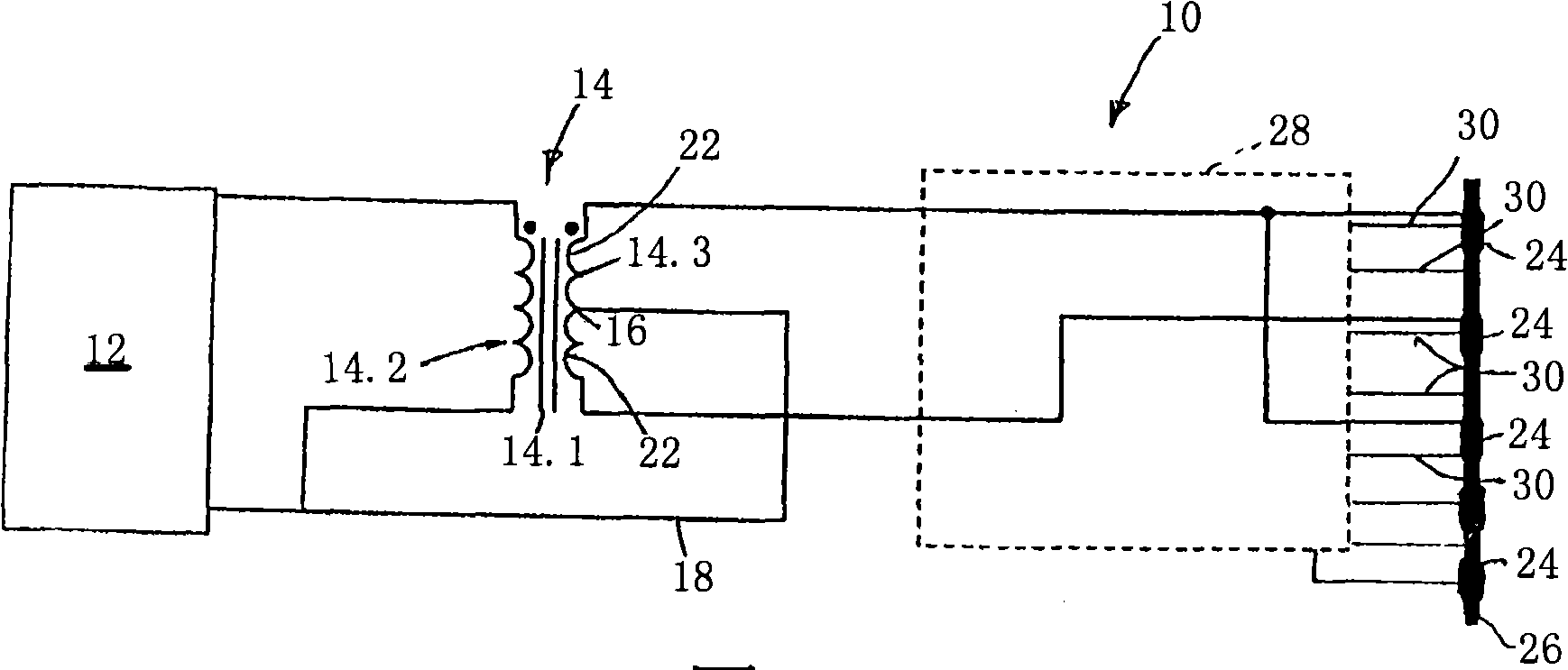
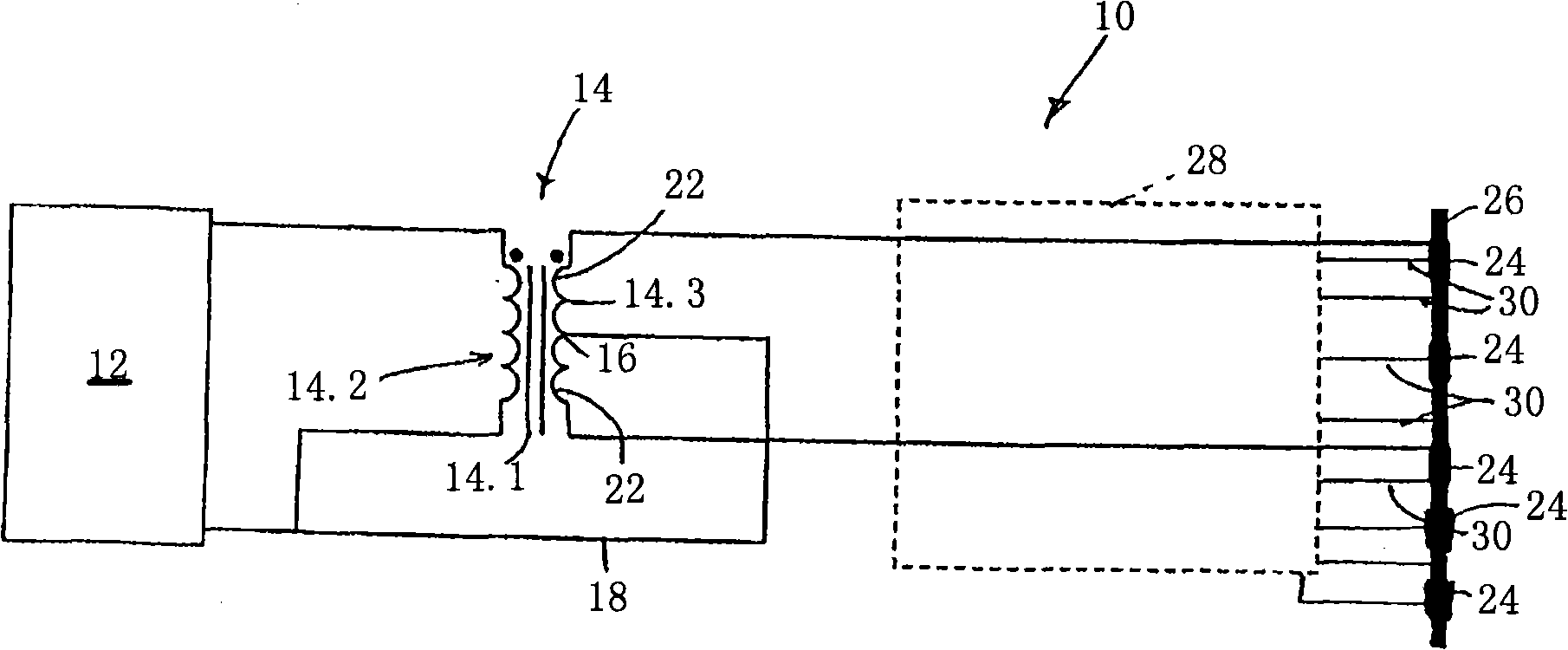
[0040]In the drawings, reference numeral 10 generally denotes a system for heating a site within a patient, according to an embodiment of the present invention. System 10 includes a generator 12 for generating electromagnetic energy, more specifically radio frequency (RF) energy.

[0041] Generator 12 communicates with transformer 14 . The transformer 14 has an iron core 14.1, a primary winding 14.2 and a secondary winding 14.3. The secondary winding 14 . 3 of the transformer 14 is a center-tapped transformer with a center tap 16 . Center tap 16 is connected to generator 12 via return line 18 .

[0042] The center tap produces two sub-windings 22, to each of which at least one active electrode 24 of a catheter 26 can be connected. By "active" is meant that unless the context clearly indicates otherwise, the electrode is used to impart energy to the site.

[0043] The arrangement of the sub-windings 22 is such that, due to the center tap 16 , the energy supplied by one sub-...


PUM


Abstract

A system 10 for heating a site in a patient's body includes a transformer 14 having a primary winding 14.2 and a secondary winding 14.3 , the secondary winding 14.3 having at least one tap 16 to provide a patient reference and at least two sources 22 of radio frequency (RF) energy, the two sources 22 of RF energy being out of phase with each other. A group of electrodes 24 is connected to the sources 22 of RF energy provided by the secondary winding 14.3 to be simultaneously energised. The arrangement is such that there are more active electrodes 24 connected to one of the sources 22 of RF energy than the other of the sources 22 of RF energy with the energy supplied to one active electrode 24 being out of phase with the energy supplied to an adjacent active electrode 24.

Description

[0001] Cross Reference Related Applications [0002] This application claims priority to US Provisional Patent Application No. 60 / 872,021, filed November 29, 2006, the contents of which are hereby incorporated by reference in their entirety. technical field [0003] The present invention generally relates to thermal treatment of biological sites in the human or animal body. More specifically, the present invention relates to systems and methods for heating a biological site within a patient to create at least one lesion at the site or for treatment of pain management. Background technique [0004] Electromagnetic energy in the form of radio frequency (RF) energy is used to create lesions at biological sites in the human or animal body for many purposes such as for myocardial ablation purposes or for tumor ablation. RF energy can also be used to heat a site for therapeutic use in pain management. In order to apply RF energy at a desired location within the body, an electro...

Claims


Application Information

Patent Timeline
IPC IPC(8): A61B18/04A61B18/12A61B18/18A61F7/12A61N5/00
CPCA61B18/1492A61B18/1206A61B2018/00434A61B2018/00577A61B2018/00702A61B2018/00791A61B2018/124A61B2018/1467
Inventor 詹姆斯·帕诺斯约瑟·L·辛库内吉
Owner CATHRX LTD
Why Eureka
Try Eureka