
Lateral clearance-free double roller enveloped worm transmission device

A technology of worm drive and double rollers, which is applied in transmission devices, gear transmission devices, mechanical equipment, etc., can solve the problems of short precision life, high relative sliding speed, and low transmission efficiency, and achieve easy precision manufacturing and processing and manufacturing , The effect of reducing friction power consumption

Inactive Publication Date: 2008-10-22
XIHUA UNIV
View PDF3 Cites 37 Cited by
  • Summary
  • Abstract
  • Description
  • Claims
  • Application Information

AI Technical Summary

Problems solved by technology

[0003] At present, there are many types of worm transmission mechanisms that have been proposed, but there are only three transmission types for worm transmissions with no backlash and adjustable backlash: "double-lead cylindrical worm transmission" (Qian Guangjin. New technology and new technology .1983 No. 5), the double-lead cylindrical worm transmission is to adjust the tooth side clearance of the transmission by adjusting the axial position of the worm to compensate for the thinning of the gear teeth. This transmission has been applied to gear hobbing machines at home and abroad. In the precision indexing mechanism, its main disadvantages are: the complex modulus hob relief grinding and precision manufacturing of the worm gear are difficult, the number of teeth that are in contact with the worm gear and the worm meshing transmission at the same time is small, the bearing capacity is low, easy to wear, and the accuracy life is short, which is difficult to meet Requirements for high-speed precision transmission or heavy-duty precision transmission
[0004] Frontal plane primary enveloping toroidal worm drive (Buckingham. Wildharber. Worm drive. Worm drive anthology. Compiled and edited by Chongqing University Worm Drive Research Group, 1976.7.), Frontal plane primary enveloping toroidal worm The contact areas on both sides of the transmission worm gear are anti-symmetrically distributed, so when it is manufactured along the wide central plane of the tooth surface, the purpose of adjusting or compensating the backlash of the tooth can be achieved by relatively rotating the two halves of the worm gear. For precision indexing worm gear transmission, its main disadvantages are: (1) the worm formed by the envelope of the positive plane, when the transmission ratio is slightly smaller, the tooth surface at the entrance of the worm will produce undercut; (2) due to the misalignment and clearance elimination , the two halves of the worm gear are in contact with the left and right tooth surfaces of the worm at the same time, and the relative sliding speed between the tooth surfaces of the worm transmission is relatively large, so the tooth surfaces are easy to wear and the transmission efficiency is low; (3) If the key is used to connect the worm wheel and the shaft, To ensure that half of the worm gear is misaligned relative to the other half of the worm gear, the keyway of the worm gear must be widened with the misalignment, which will bring inconvenience to the adjustment of the backlash of the transmission
For example, the patent application number is 200610102244.6 "precision worm gear transmission anti-backlash device", the patent application number is 200510050421.6 "a kind of worm gear transmission device", the patent number is ZL99117383.X "planar enveloping toroidal worm with adjustable backlash Although these transmissions can eliminate backlash, they have many transmission elements, large volume, and complex structure, which are difficult to apply to the transmissions of servo drive systems that require high transmission precision, large load capacity, and compact structure.

Method used


Image

  • Lateral clearance-free double roller enveloped worm transmission device
  • Lateral clearance-free double roller enveloped worm transmission device
  • Lateral clearance-free double roller enveloped worm transmission device

Examples


Embodiment Construction

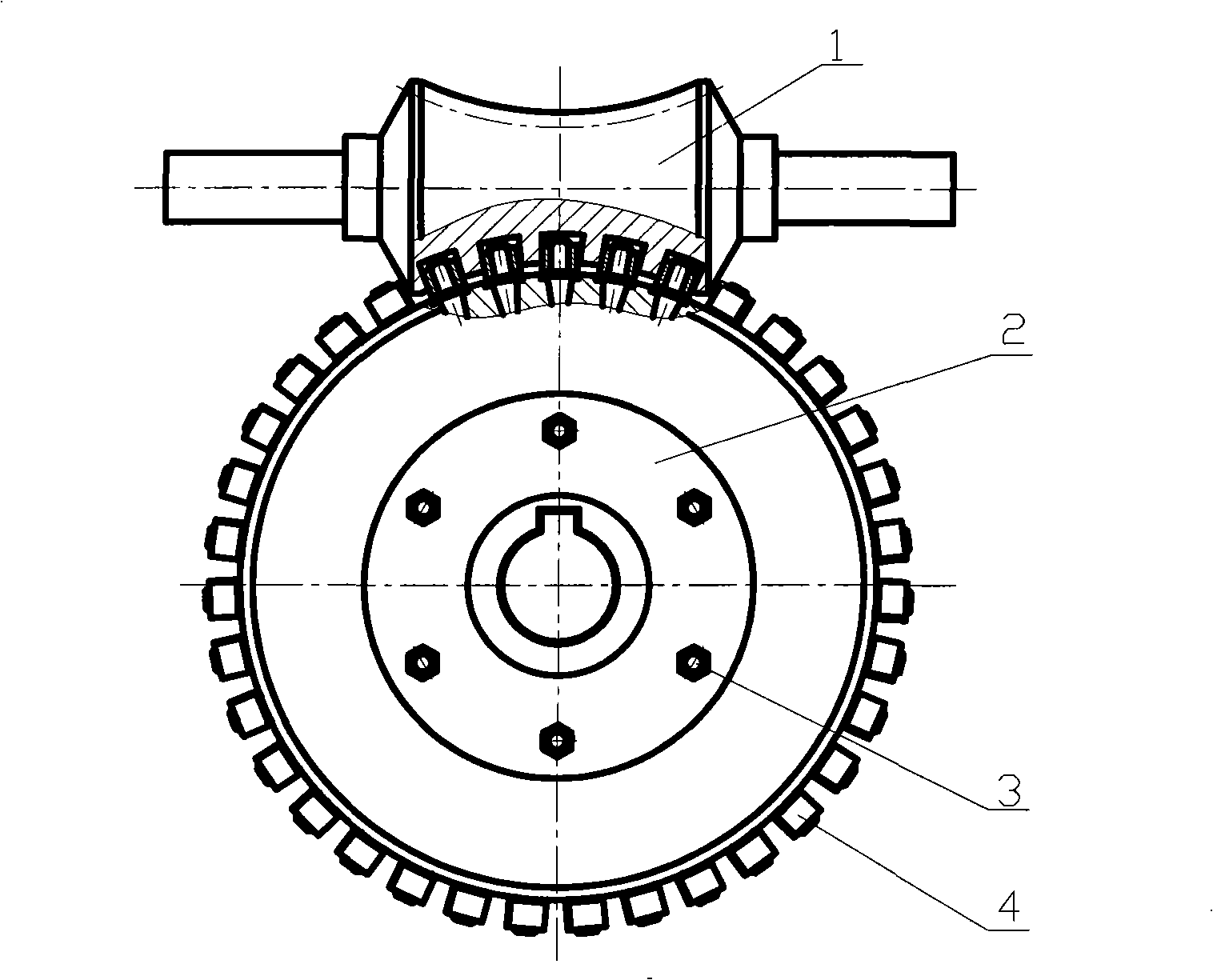
[0024] The structure and working principle of the embodiment of the backlash-free double-roller enveloping toroidal worm transmission mechanism of the present invention will be described in detail below in conjunction with the accompanying drawings.

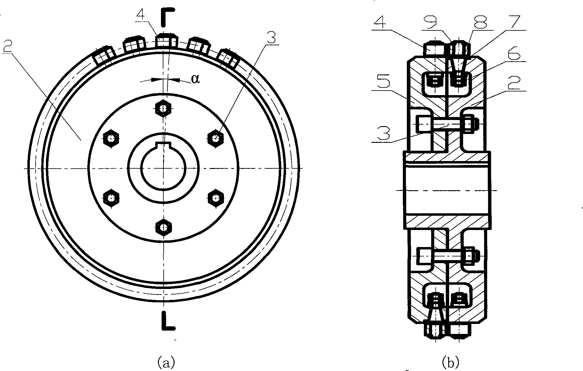
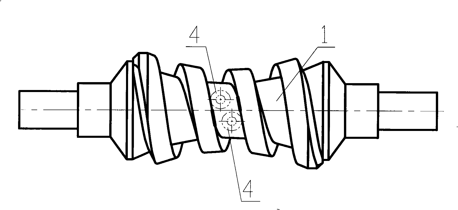
[0025] Such as figure 1 Shown is the worm gear structure diagram of the embodiment of the backlash-free double-roller enveloping toroidal worm drive mechanism. The backlash-free double-roller enveloping toroidal worm transmission mechanism of the present invention is composed of a worm 1 and a worm wheel formed by one-time enveloping with the roller side as the tool mother surface. Such as figure 2 As shown, the worm wheel is composed of a right half-wheel body 2 and a left half-wheel body 5, and cylindrical rollers 4 are uniformly arranged in the radial direction, and the right half-wheel body 2 can rotate along its center of rotation relative to the left half-wheel body 5, The two are misplaced and installed, and are fastene...


PUM


Abstract

The invention discloses a backlash-free double rollers enveloping worm gear, a worm wheel of the transmission mechanism comprises two half worm wheels, the rollers are uniformly distributed in circumferential direction of each half worm wheel, the rollers rotate on the rotation axes; the two rows of rollers are arranged alternatively, wherein, one row of the rollers are engaged with left flank of the worm, the other row of rollers contact the right flank of the worm; the left and right flanks of the worm are respectively enveloped by rollers which are arranged at appropriate positions on the top and bottom of the main plane; through the adjustment of the mounting positions of the two half worm wheels, the rollers can always be in contact with the flank of the worm ,so as to achieve no backlash transmission. The transmission mechanism eliminates the return error of the transmission, makes the transmission smooth and improves the accuracy of transmission. The invention has the advantages of simple structure, easy manufacture, low cost and good economy, is a novel worm transmission device combining precision transmission and power transmission, is capable of being used for precision indexing, precision transmission and precision power transmission.

Description

technical field [0001] The invention belongs to the technical field of mechanical transmission, in particular to a backlash-free toroidal worm transmission mechanism in worm transmission. Background technique [0002] In gear transmission, proper tooth backlash is one of the necessary conditions for the normal operation of the transmission mechanism. The existence of backlash can avoid the extrusion or jamming caused by the expansion of gear teeth due to force deformation and frictional heat; it can compensate manufacturing and assembly errors to a certain extent, so that a more economical manufacturing process can be used; it can provide accommodation The space for lubricating oil is convenient for tooth surface lubrication, etc. However, due to the existence of tooth backlash, it will inevitably bring shock, vibration, noise, and reduce system follow-up accuracy and stability to modern electromechanical systems such as industrial robots, CNC machine tools, printing equipm...

Claims


Application Information

Patent Timeline
IPC IPC(8): F16H1/16F16H55/22F16H55/24
Inventor 王进戈张均富洪雷
Owner XIHUA UNIV
Learn More