Microfluidic control chip for cell immobilization and solution dilution

A technology of solution dilution and cell fixation, which is applied in the fields of bioengineering and analytical chemistry, can solve the problems of difficult design and not many uses, and achieve the effects of being conducive to popularization, low cost, and convenient operation

Inactive Publication Date: 2008-10-22
CHONGQING UNIV
View PDF0 Cites 16 Cited by
  • Summary
  • Abstract
  • Description
  • Claims
  • Application Information

AI Technical Summary

Problems solved by technology

This commutation method needs to process staggered channels in the upper and lower two-layer chip stru...

Method used


Image

  • Microfluidic control chip for cell immobilization and solution dilution
  • Microfluidic control chip for cell immobilization and solution dilution
  • Microfluidic control chip for cell immobilization and solution dilution

Examples


Embodiment 1

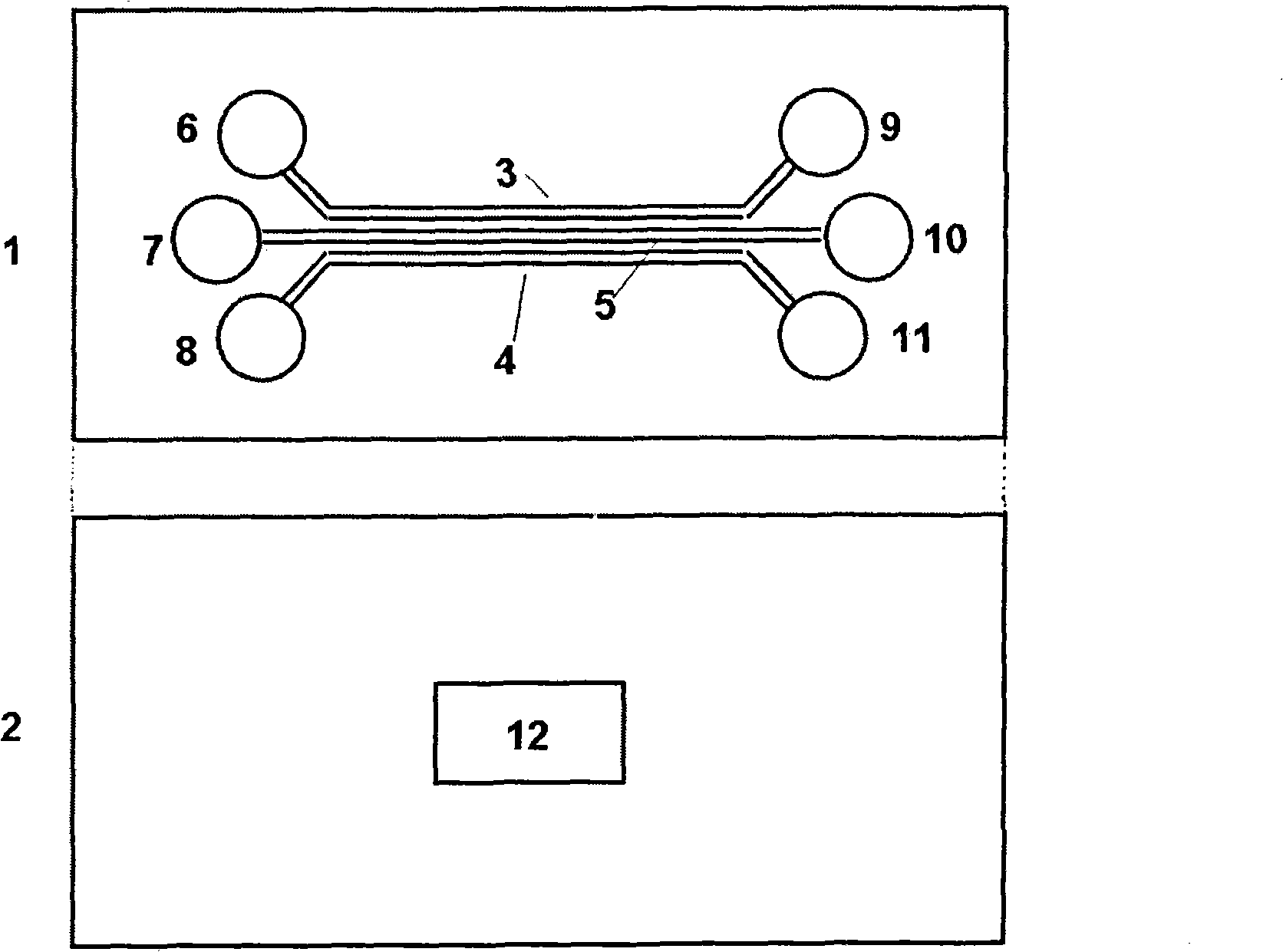
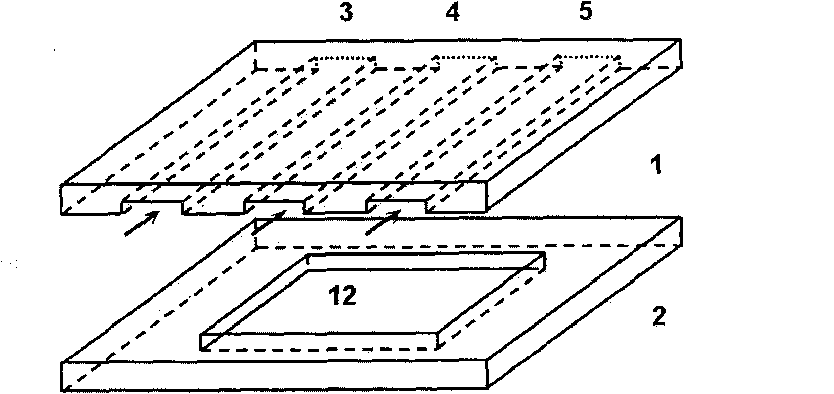
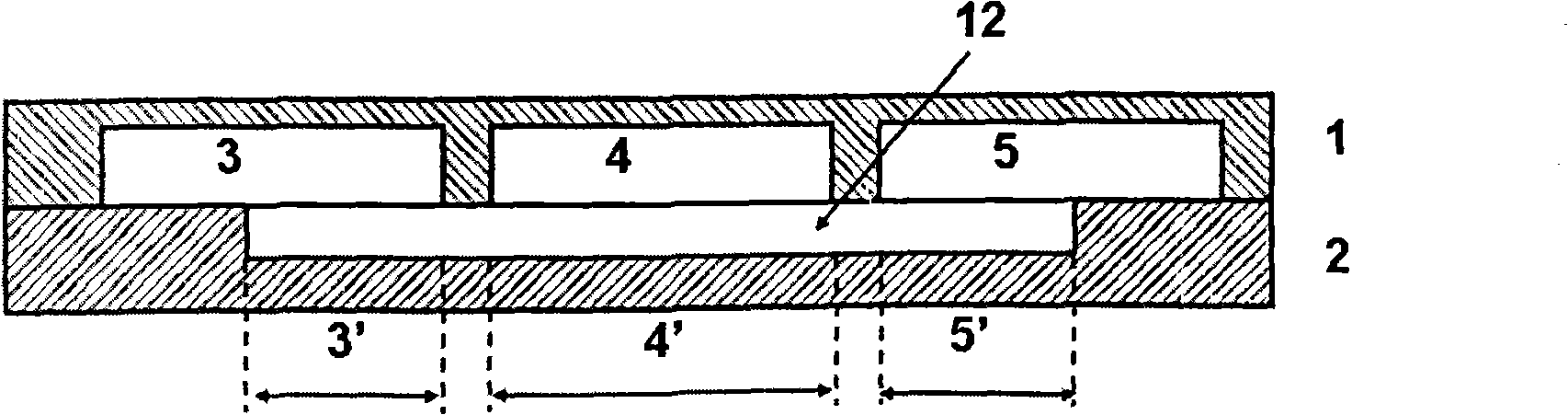
[0026] see figure 1 , figure 2 and image 3 , The microfluidic chip is composed of two layers, the first layer is a transparent hard base layer 1 made of glass, and the second layer is a transparent elastic rubber layer 2 made of PDMS. One side of the transparent hard base layer 1 is processed with three parallel microchannels 3, 4, 5, and there are sample inlets 6, 7, 8 and sample outlets 9, 10, 11 at both ends of the microchannels. Driven by the micropump, the sample liquid can enter the microchannel from the sample inlet 6, 7, 8, and then flow out from the sample outlet 9, 10, 11. One side of the transparent elastic rubber layer 2 is processed with cuboid-shaped grooves to form a micro-water pool 12. The length and width of the micro-water pool 12 are different according to different application purposes. Before combining, treat the transparent elastic rubber layer 2 with oxygen plasma for 30 seconds, and then place it horizontally with the micro-water pool 12 facing up...

Embodiment 2

[0028] Example 2: Immobilizing cells using micro-pool chip structure

[0029] The human promyelocytic leukemia cell HL 60 suspension was respectively added from the injection ports 6, 7, and 8 of the chip described in Example 1, and a pressure of 40 Pa was applied to the injection ports by a micropump, and the outlet pressure was 0.

[0030] When the transparent elastic rubber layer 2 is combined with the transparent hard base layer 1, the symmetrical midline of the micro-water pool 12 coincides with the symmetrical midline of the middle microchannel 4. When the width of the micro-water pool 12 is greater than or equal to 340 μm (the width of 3 micro-channels adds the interval between them), after the liquid from the micro-channels 3, 4, 5 is full of the micro-water pool 12, there is no liquid to flow in or out. Micro-basin 12, therefore, there is also no lateral flow through micro-basin 12 and immobilization of cells, as shown in FIGS. 4A and 4B of FIG. 4 .

[0031]As shown ...

Embodiment 3

[0033] Embodiment 3: Utilize this chip to carry out solution mixing

[0034] In a microfluidic system, the flow of liquid is mainly laminar flow, and material diffusion is the main mixing mode. The degree of mixing is directly proportional to the diffusion coefficient and diffusion (residence) time of the substance, and inversely proportional to the diffusion distance, and the mixing speed is also inversely proportional to the diffusion distance.

[0035] In the solution dilution experiment, the fluorescent ethidium bromide solution is added from the chip inlet 4, and three-distilled water is added from the inlet 3 and 5. Under the pressure, different solutions flow from the inlet to the outlet. The flow and diffusion of ethidium bromide molecules in the microchannel can be obtained by laser confocal microscope detection.

[0036] Where the microchannels 3 , 4 , 5 contact the micro-water pool 12 , liquid can enter the micro-water pool 12 . Fluids from different microchannels...


PUM


Abstract

The invention provides a micro-fluidic chip used for cell immobilization and solution dilution. The invention comprises a transparent hard substrate layer one surface of which is provided with a plurality of microchannels by means of machining, and also comprises a transparent elastic rubber layer one surface of which is provided with micro-water pools by means of machining, wherein, the one surface of the transparent hard substrate layer which is provided with the microchannels by means of machining closely clings to the one surface of the transparent elastic rubber layer which is provided with the micro-water pools by means of micro-machining; the microchannels are overlapped with the micro-water pools to form a closed cell suspension or a solution flowing path; the dimension of the prior micro-water pools is changed through selection of different structures of the micro-water pools or through external force, thereby the flow condition of the whole chip can be controlled and cell immobilization of solution dilution are realized. The micro-fluidic chip can be used on a microchip to immobilize different biological living cells or abiological particles and then realize bioanalysis by taking the cells and molecules as the basis; simultaneously, the micro-fluidic chip can control different types of solution and mix the solution according to the set proportion and the diffusion conditions, and then the solution concentration or the concentration gradient required is obtained; and the micro-fluidic chip is used for high-flux biological sample analysis.

Description

technical field [0001] The invention belongs to the technical field of bioengineering and analytical chemistry, and specifically relates to a microfluidic chip structure for cell analysis, mixing of biological and chemical reaction solutions, and generation of concentration gradients. Background technique [0002] In recent years, microfluidic chip technology has been more and more widely used in the field of analytical chemistry and biochemical detection. Among them, cell analysis and solution mixing operation (including quantitative dilution and concentration gradient generation) are two important application directions. In many on-chip cell analysis methods, arranging and fixing cells in a certain position is a prerequisite for further biochemical detection. The solution in the chip is diluted or quickly mixed according to a certain ratio, and the required reaction concentration, component distribution ratio or concentration gradient can be obtained, and the reaction spe...

Claims


Application Information

Patent Timeline
IPC IPC(8): G01N33/50C12Q1/02
Inventor 杨军王敏李圆怡张丽果刘向绍翟盛杰郑小林
Owner CHONGQING UNIV
Why Eureka
Try Eureka