Spark generation method and ignition system using same

An ignition system and spark technology, applied in spark ignition controllers, circuits dedicated to spark gaps, spark gaps, etc., can solve the problems of reducing sinusoidal output voltage and complex high-frequency ignition systems.

Inactive Publication Date: 2008-10-22
VIMX TECH INC
View PDF4 Cites 16 Cited by
  • Summary
  • Abstract
  • Description
  • Claims
  • Application Information

AI Technical Summary

Problems solved by technology

High frequency ignition systems are complex and produce a sinusoidal output voltage that reduces effective plasma formation in the spark gap

Method used


Image

  • Spark generation method and ignition system using same
  • Spark generation method and ignition system using same
  • Spark generation method and ignition system using same

Examples


Embodiment Construction

[0023] In the description below, the term "on" is used for a switch when the switch is conducting current, and "off" is used when the switch is not conducting.

[0024] The terms continuous discharge and continuous spark discharge are used herein to mean a continuous spark across the spark gap during the duration of combustion (eg, the combustion stroke of the engine). Successive spark discharges will span multiple, and often many, cycles of energy storage and release of the charge storage device within the ignition circuit.

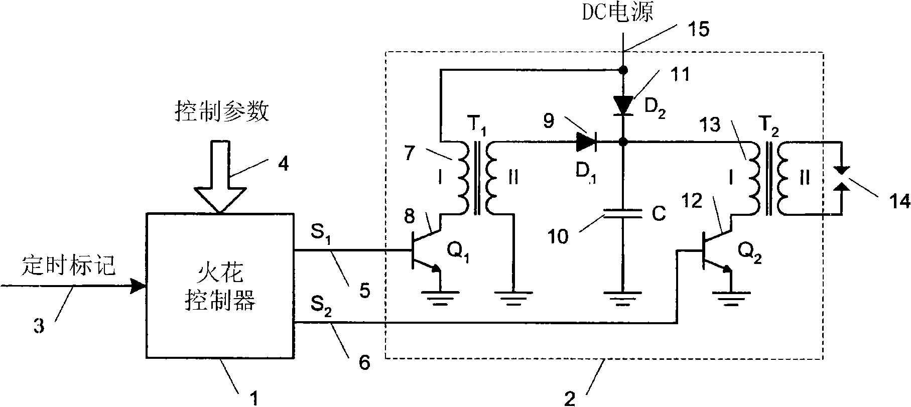
[0025] see figure 1, showing a circuit diagram of an ignition system according to an embodiment of the present invention. The ignition system comprises a spark controller 1 which provides a first control signal along conductor 5 and a second control signal along conductor 6 . Along conductor 5 a first control signal is provided for controlling the storage coil switch 8 and along conductor 6 a second control signal is provided for controlling the igniti...


PUM


Abstract

An ignition system providing power and duration controlled ignition spark, comprises a spark controller, first switching energy accumulator, storage capacitor, and second switching energy accumulator with an ignition coil. The ignition system utilizes dual means of switching energy accumulation, internal energy transfer, and three means of energy release to the ignition spark, working in all possible combinations managed by means of the spark controller depending on engine operating conditions, and provides continuous bipolar ignition spark. Spark profile is regulated by means of control signals (2) and (3) based on their frequency, duty cycle, interrelation, and running time.

Description

technical field [0001] This invention relates generally to internal combustion engines, and more particularly to generating a spark for an internal combustion engine. Background technique [0002] Internal combustion engines are well known. During the operating cycle of the engine, fuel and air are drawn into the combustion chamber by the piston moving away from the inlet of the combustion chamber, the fuel is then compressed by the movement of the piston in the opposite direction (toward the inlet), the spark ignites the fuel, The piston is thus forced away from the inlet, and the combustion chamber is then partially emptied by the movement of the piston eventually towards its exhaust port near the inlet end. Although according to the theory of a simplistic ideal, a single spark would consume all the fuel in the combustion chamber in a near-instantaneous manner, in reality this is not the case. [0003] Two prior art ignition systems that are very commonly used are induct...

Claims


Application Information

Patent Timeline
Patent Type & Authority Applications(China)
IPC IPC(8): H01T15/00F02P15/00F02P9/00
CPCF02P3/0853F02P15/12F02P3/0846F02P15/10F02P15/08F02P15/00H01T15/00
Inventor 阿雷山大·朴尼克
Owner VIMX TECH INC
Why Eureka
Try Eureka